TOSHIBA RBM-FGUS1P-E Heat Exchanger Fin Guard Option Kit Installation Guide
- June 16, 2024
- Toshiba
Table of Contents
Air conditioner packaged unit
Outdoor unit
HEAT EXCHANGER FIN GUARD
INSTALLATION MANUAL
Model
RBM-FGUS1P-E, RBM-FGUM1P-E
RBM-FGUS1P-E Heat Exchanger Fin Guard Option Kit
Thank you very much for purchasing Heat exchanger fin guards for TOSHIBA air conditioner packaged unit. Please read this Installation Manual to install the fin guards, and perform correct works.
SAFETY PRECAUTIONS
- Please read this “SAFETY PRECAUTIONS” carefully to install the fin guards before starting work.
- The precautions listed here are important safety information, which must be strictly adhered to.
- After completing the installation, make sure that the unit operates properly during the trial run.
Also, inform customers that they should store this Installation Manual along with the user’s manual and Installation Manual of the main unit of the air conditioner.
WARNING| Be sure only agent or qualifi ed service personnel to install the
equipment.
Improper installation yourself will cause the fin guard to fall and result in
injury.
---|---
CAUTION| Install accordingly to this installation instructions strictly.
If installation or install processing is defective, it will cause refrigerant
gas leakage or injury.
CAUTION FOR INSTALLING
CAUTION| Install the fin guards only at position where screw holes locate.
Do not open screw holes yourself, not use screws other than specifi ed for
installation. It will damage the heat exchanger, or cause malfunctions of
electrical components or electronic components.
---|---
Be careful so as not to damage the fins and the pipes during the installation.
The pipe damage will cause refrigerant gas leakage.
Clean up the metal dust after the installation. Also, rust proof the
installation location. The uncleared metal dust after the installation or not
rustproofed installation location will cause rust to form.
Wear gloves ( ) during the installation work.
Otherwise, it will cause injury on the parts. ( Thick gloves like work gloves
)
SPECIFICATIONS
| RBM-FGUS1P-E, RBM-FGUM1P-E
---|---
Wire material| Material : SWRM3, Wire diameter Ø3.5
Surface treatment| Polyethylene coating (Colour : Silky shade·munsell
No.1Y8.5/0.5)
PARTS
(It contains the below parts.)
| No. | Item | Model (RBM-) | |
|---|---|---|---|
| FGUSIP-E | FGUMIP-E | ||
| C) | Heat Exchanger fin guard (Right) | 1 | |
| 2) | Heat Exchanger fin guard (Left) | 1 | |
| C) | Heat Exchanger fin guard (Rear) | ||
| 1 | 2 |
1
0| Mounting screw (M5)
(M5x16 with washer)| | 20| 23
(6)| Installation Manual| This book| 1| 1
C)| Mounting screw (drill screw) (04.2x13L)| | 7| 11
INSTALLATION METHOD
- Heat exchanger fin guard (left, right) installation
RBM-FGUS1P-E 990W body Right Side View
- Before the installation, remove the 3 fixing screws in the right side of the side board.
- Insert the 6 mounting screws 4 (M5×16 with washer) into the 6 screws hole
in the side of the outdoor unit and fasten to fix the heat exchanger fin
guard.
 RBM-FGUS1P-E 990W body Left
Side View
RBM-FGUS1P-E 990W body Left
Side View
RBM-FGUM1P-E 1290W body Both Side View - Insert the 6 mounting screws 4 (M5×16 with washer) into the 6 screws hole
in the side of the outdoor unit and fasten to fix the heat exchanger fin
guard.
 If missing drilling holes,
Please use 6 drill screw Ø4.2×13 instead to both side L and R.
If missing drilling holes,
Please use 6 drill screw Ø4.2×13 instead to both side L and R.
After completing the fin guard installation, make sure that the fin guard is fixed firmly without looseness, ratting or chatter. When the looseness, ratting or chatter observed, adjust the screws so that the wires will stretch to a certain extent.
- Heat exchanger fi n guard (rear) installation
RBM-FGUS1P-E 990W body
1) Insert the 6 mounting screws 4 (M5 × 16 with washer) into the 6 screws holes in the rear side pillars of the outdoor unit and fasten to fix the heat exchanger fin guard.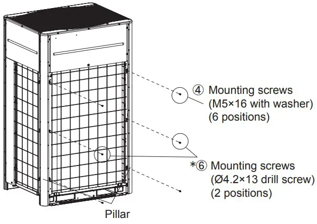* If missing drilling holes,
Please use 6 drill screw Ø4.2×13 instead to rear side.
After completing the fin guard installation, make sure that the fin guard is fixed firmly without looseness, ratting or chatter. When the looseness, ratting or chatter observed, adjust the screws so that the wires will stretch to a certain extent.
RBM-FGUM1P-E 1290W body
1) As shown in the below figure, pinch the top panel and the bottom plate with wires in the top center and bottom center to hold.
Place 2 top center and bottom center wires on the outside of the top panel and the bottom plate, while insert 2 outer top and bottom wires into the inside of top panel and the bottom plate to hold.
- Insert the 6 mounting screws 4 (M5×16 with washer) into the 6 screws holes in the rear side pillars of the outdoor unit and fasten to fix the heat exchanger fin guard.
- Insert the 3 mounting screws 6 (drill screws) (Ø4.2×13) to fi x rear side
center pillar of outdoor unit.

INSTALLATION SPACE FOR OUTDOOR UNIT
Ensure suffi cient free space surrounding the outdoor unit. If installing the unit without leaving this space, the protective function may be activated and cease the operation. For details, follow the instructions as described in the outdoor unit Installation Manual.
INSTALLATION CONFIRMATION
After completing the installation, make sure that the unit operates properly during the trial run.
1140701001-1
Read User Manual Online (PDF format)
Read User Manual Online (PDF format) >>