R TEC AUTOMATION Wall Box Mount Switch User Guide
- June 7, 2024
- R TEC AUTOMATION
Table of Contents
![]()
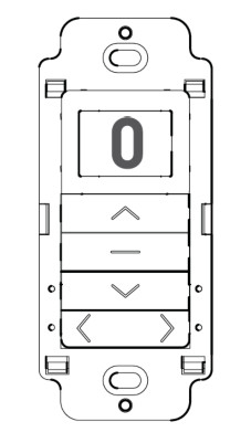
R-TEC Smart Controls – Wall Box Mount Switch
RTMWSR15C

Wall Box Mount Switch in cut in configuration provides a sensible control
option for individual room and whole home window treatment control.
Available in 15 channel model, wall switches are compatible with all ARC
motors.
Cut in wall switches feature a contemporary design and a wirefree deployment,
making them retrofit ready for any location.
FEATURES – 15 CHANNEL

COMPLIANCE STATEMENT
This device complies with part 15 of the FCC Rules. Operation is subject to the following two conditions:
- This device may not cause harmful interference.
- This device must accept any interference received, including interference that may cause undesired operation.
TECHNICAL DATA / PACK CONTENTS
PRODUCT SPECIFICATIONS
| Parameters | Value |
|---|---|
| Voltage | 3 V DC |
| Battery | 2 x AAA |
| Radio Frequency | 433.92 MHz |
| Transmitting Power | 10 milliwatt |
| Transmission Range | 65′ |
| Temperature Working Range | 14º F – 122º F (-10º C – 50º C) |
PACK CONTENTS
- Wall Box Mount Switch, 15 Channel
- Wall Fixing Screws (2) and Anchors (2)
- Instruction Manual
- 1.5 V AAA Batteries (2)
- White Single Gang Decorator Style Wall Plate with Mounting Screws (2)
SAFETY
WARNING
Any changes or modifications to this unit not expressly approved by the party
responsible for compliance could void the user’s authority to operate the
equipment. Incorrect installation can lead to serious injury and will void
manufacturer’s liability and warranty.
CAUTION
- Do not expose to moisture or extreme temperatures.
- Do not allow children to play with this device.
- Use or modification outside the scope of this instruction manual will void warranty.
- Installation and programming to be performed by a suitably qualified installer.
- Use only R-TEC Automation® hardware.
- Keep clear when in operation.
- Replace battery with correctly specified type.
IMPORTANT SAFETY INSTRUCTIONS TO BE READ PRIOR TO OPERATION
- It is important for the safety of persons to follow the enclosed instructions. Save these instructions for future reference.
- Persons (including children) with reduced physical, sensory or mental capabilities, or lack of experience and knowledge should not be allowed to use this product.
- Frequently inspect for improper operation. Do not use if repair or adjustment is necessary.
- Keep away from children.
INSTALLATION
INSTALL SWITCH BATTERIES

Replace cover by sliding into place.
MOUNT SWITCH
Use supplied fasteners and anchors as needed to attach base.

FUNCTIONAL OVERVIEW
BUTTONS

SELECTING A CHANNEL

****IMPORTANT
Please refer to the relevant documentation of your motor model for instructions on adjusting motor settings.
GROUP CONTROL USING CH “0”
Channel “0” is preset to control ALL window treatments paired within your
multi channel switch. To create a customized group channel, reference page 9.
 HIDE UNUSED CHANNELS
Your multi channel switch can be configured to have anywhere between 1 or 15
visible channels. Inactive channels will not be visible when scrolling through
the < > selections.

LOCK LIMIT SETTING
The 15 channel switch uses the LCD screen to notify the user when the lock
feature has been activated.


PROGRAMMING
USING MOTOR P1 BUTTON
IMPORTANT
Multiple motors can be grouped onto shared channels for coordinated control.
- Confirm that motor limits and favorite position are already set for each individual motor.
- Ensure that each motor you want to group is also assigned to another channel by itself.


USING PRE-EXISTING CONTROLLER
A = Existing switch or channel (to keep). B = Switch or channel to add or
remove.

TROUBLESHOOTING
| Problem | Cause | Remedy |
|---|---|---|
| Motor is not responding | Switch battery is discharged | Replace battery. |
| Battery is inserted incorrectly | Check battery polarity. | |
| Radio interference / Shielding | Ensure switch is positioned away from metal |
objects and that aerial on motor or receiver is kept straight and away from
metal.
Receiver distance is too far from switch| Move switch to a closer position.
Power failure| Check power supply to motor is connected and active.
Incorrect wiring| Check wiring is connected correctly (refer to motor
installation instructions).
Cannot set limits on a single motor (multiple motors respond)| Using “Group”
channels to
adjust motor limits
Red LED is solid
| Check wiring is connected correctly (refer to motor installation
instructions).
SYSTEM BEST PRACTICE – Provide an extra 15 channel switch in your multi motor
projects, that provides individual control for each motor for programming
purposes.
Any Questions?
Contact our R-TEC Automation® in-house experts at 866.985.3423. Email us at
RTECAutomation@RowleyCompany.com.
© 2021 Rowley® Company. All rights reserved. R-TEC Automation® is a registered trademark of the Rowley® Company, LLC.
Do no dispose of in general waste.
Please recycle batteries and damaged electrical products appropriately.

Read User Manual Online (PDF format)
Read User Manual Online (PDF format) >>