VALEMO V-2 Motorised Zone Valve User Manual
- September 18, 2024
- VALEMO
Table of Contents
- Introduction
- Valve Specifications
- Actuator Specifications
- Construction and Operation
- Application
- Installation
- Actions of Normally Closed (N.C.) Valves
- Manual Open without Electric Power
- Disassembly of an Actuator from a Valve Body
- Assembly of an Actuator to a Valve Body
- Safety & Caution
- Customer Support
- References
- Read User Manual Online (PDF format)
- Download This Manual (PDF format)
VALEMO V-2 Motorised Zone Valve

Introduction
Valemo V-Series motorised zone valves have been recognized globally by
professionals and consumers alike for fast and easy installation, trouble free
operation and complying to today’s highest industry standards. We offer 2-way
and 3-way valves with 1/2″, 3/4”and 1″ BSP connection to European customers.
These are perfect replacement options of with other popular brand valves in
the market.
Valve Specifications
| Valve type: | 2-way on/off, 3-way on/off/diverting |
|---|---|
| Connection | BSP 1/2″ 3/4″, 1″ |
| Materials: | Body: forged brass Stem: brass with nickel-plated Seals: |
EPDM/NBR
Static pressure:| 20 Bar
Medium:| water and glycol (up to 50%)
Media temperature range:| 0-100 C
Close off pressure:| 1.38-3.45 Bar
Kv:| 2.2 (1/2″) 3.0 (3/4″ ) and 5.0(1″ )
Actuator Specifications
| Voltage | 230VAC, 50HZ, optional 24 VAC (custom order) |
|---|---|
| Power consumption: | 6.5W, 7 VA |
| Wire leads: | 5 wires (with micro switch) 2 wires (without micro switch) |
| End switch : | 1 X SPST, red |
| Motor running time: | Power on:10-15 seconds Spring return: 4-5 seconds |
| Humidity: | : 5% to 95% non-condensing |
| Ambient temperature: | 0-50 C |
| Housing: | stainless steel base with Al cover |
Construction and Operation
Motorised zone valves are used in heating and air-conditioning systems to control the flow of hot or chilled water. A valve consists of a spring-return actuator that is attached to a 2-port or 3-port valve body. When power is applied, a synchronous motor inside the actuator winds the spring and moves the valve paddle to a desired position. When power is off, the spring returns the paddle to its initial position.
Application
A motorised zone valve is designed for cycling (not constantly powered on) applications. It is typically used on fan coil units, baseboards or other closed loop hydronic systems,but is not suitable for open loop systems where there is exposure to fresh air, which will result in damage to the rubber seal inside the valve by dissolved oxygen.
Model Numbering System for V-series Zone Valves and Spring Return Actuators

Installation
-
Read the instructions carefully, make sure valve specifications on the product label is suitable for the application.
-
A valve can be mounted vertically or horizontally, but can never be turned upside down so that the powerhead is below the horizontal level of the pipework.
-
For Compression type, attach a spanner (32mm) on the valve body at each port, while tightening up the nuts. Tighten compression nuts to make a watertight seal but be careful not to overtighten. Do not grip the powerhead while making and tightening up plumbing connections.

2-port valves can be installed on the supply side or the return side (preferred). The media through the valves must be from port B to port A (stamped on valve body). It is also indicated by an arrow on the valve body, to make sure the paddle closes against the flow.

3-port valves can be installed on the supply side or the return side. -
3-port valves use only normally closed (N.C.) actuators.
-
Rotate valve bodies 180 degree for normally open (N.O.) applications.

Actions of Normally Closed (N.C.) Valves
| 2-way| 3-way
---|---|---
N.C. power OFF| Port B closed| Port B closed, Port A opened, Port AB opened
N.C. power ON| Port B opened| Port B opened, Port A closed, Port AB opened
N.C. manual ope| Port B opened| Port B opened, Port A closed, Port AB opened
Wiring
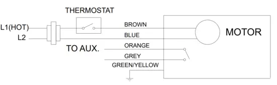
- 5 wires for valves with end switch.
- 2 orange wires for valves without end switch.
Manual Open without Electric Power
For system drain own and filing purposes, and to remove an actuator from a valve body, a manual open status should be achieved by pushing the manual open lever slowly and firmly from right to left and pressing it to a locked position. When power is applied, the manual open lever will unlock itself automatically. End switch function will not be triggered when a valve is manually opened.
Disassembly of an Actuator from a Valve Body
- Move the manual open lever to “OPEN” position and lock the lever.
- Move the actuator release lever from right to left and hold it, so the actuator and the valve can be Valemo Controls Limited separated.
Assembly of an Actuator to a Valve Body
- Move the manual open lever to “OPEN” position and lock the lever.
- Align the angle of the valve stem to insert it half way to the hole of the actuator.
- Move the actuator release lever from right to left and hold it, and insert the valve stem fully into the actuator.
- Release the actuator release lever.
Safety & Caution
 Failure to follow these instructions
may cause personal injury or property damage!
Failure to follow these instructions
may cause personal injury or property damage!
Valemo shall not be liable for injuries and damages resulting from misuse of
its products.
Caution:
Installers must be trained, experienced service technicians and comply with
local codes and ordinances.
Caution:
Disconnect power supply before connecting wires to prevent electric shock or
equipment damage.
Caution:
Over-tighting with use of Teflon pipe joint compound will result in potential
breakage of joints. Teflon provides lubricity so care must be exercised not to
overtighten joints.
Caution:
Avoid installation in locations with excessive moisture, explosive vapors,
corrosive fumes or vibration.
Warning:
System fluids are under pressure and its temperature may be high. Be sure the
pressure is reduced to zero and the system temperature is below 38C during
installation.
Customer Support
Valemo Controls Limited
hello@valemocontrols.com
www.valemo-eu.com

References
Read User Manual Online (PDF format)
Read User Manual Online (PDF format) >>