ThreeSixty AMB52 Ambience DC Ceiling Fan Owner’s Manual
- June 15, 2024
- ThreeSixty
Table of Contents
- Important Information
- Fan Technology That’s Innovative and Reliable
- Important Safety Instructions
- Additional Safety Instructions
- Supplied parts
- Tools and materials required
- Installation issues, missing or damaged parts
- Installing the fan
- Exploded Fan View & Parts
- Caring for and operating your remote control
- Blade balancing
- Care and cleaning
- ThreeSixty Fans – Plain English Warranty Terms
- Customer Support
- References
- Read User Manual Online (PDF format)
- Download This Manual (PDF format)
ThreeSixty AMB52 Ambience DC Ceiling Fan

Important Information
Please read and keep these instructions as they contain assembly, warranty, maintenance and service information.
Net Weight: 8 kg
** denotes colour on box
Fan Technology That’s Innovative and Reliable
ThreeSixty Ceiling Fans is proud of its range of ceiling fans, accessories and lighting products. We believe these are the leading products in their category, reflecting over 40 years collective Australian experience in design, development, manufacturing and distribution of electronics and electrical equipment.
The Ambience DC ceiling fan is a modern design engineered for bedroom comfort. Providing effective levels of airflow optimised for bedrooms and small living areas. The Ambience DC is available in 48” (122 cm) and 52” (132 cm) sizes to suit most Australian bedrooms, and is also a great choice for living areas. With a built-in and dimmable up light that provides gentle ambience for your room for times you don’t need the full downlight brightness. Includes a 6-speed remote control and has an optional 17W CCT Dimmable LED Downlight Kit for those times you want your ceiling fan to also be a light source.
Our manufacturing is subject to strict quality control and we back our products with a plain English warranty. Any problem caused by a fault in the product will be fixed or replaced with the least possible inconvenience.
We welcome feedback and suggestions. By listening to our customers we aim to continuously improve our products and services.
Electricians and installers:
We are here to help you. Please call our support line if you have any
questions or need assistance with installing or wiring the product.
Customers and purchasers:
Please call us if you have any questions about your fan or would like advice
on the best way to use your fan to save energy.
Important Safety Instructions
WARNING: To avoid fire, shock and serious personal injury, follow these instructions.
- Read your owner’s manual and safety information before installing your new fan. Review the accompanying assembly diagrams.
- Before servicing or cleaning unit, switch power off at fuse box / circuit breaker and lock box (disconnecting means to prevent power from being switched on accidentally).
- Be careful of the fan and blades when cleaning, painting, or working near the fan. Always turn off the power to the ceiling fan before servicing.
- Do not insert anything into the fan blades while the fan is operating.
- Do not operate reversing switch until fan blades have come to a complete stop.
- Do not dispose of electrical appliances as unsorted municipal waste, use separate collection facilities.
- Contact your local government for information regarding the collection systems available.
- If electrical appliances are disposed of in landfills or dumps, hazardous substances can leak into the groundwater and get into the food chain, damaging your health and well-being.
- This appliance is not intended for use by persons (including children) with reduced physical, sensory or mental capabilities, or lack of experience and knowledge, unless they have been given supervision or instruction concerning use of the appliance by a person responsible for their safety.
- Children should be supervised to ensure that they do not play with the appliance.
Additional Safety Instructions
- To avoid possible shock, be sure electricity is turned off at the fuse box before wiring, and do not operate fan without blades.
- All wiring and installation procedures must comply with AS/NZS 3000 Wiring Rules and any other local regulations. The ceiling fan must be grounded as a precaution against possible electrical shock. Electrical installation must be made by a licensed electrician.
- The fan base must be securely mounted and capable of reliably supporting at least four times the weight of the ceiling fan. The installation and replacement of the suspension system must be completed by the manufacturer, its service agent or a suitably qualified person.
- The fan must be mounted with the fan blades at least 2.1 meter (lowest edge) from the floor to comply with safety regulations and to prevent accidental contact with the fan blades.
- Follow the recommended instructions for the proper method of wiring this ceiling fan.
- This fan must be installed with an isolation switch or a device to disconnect all poles.
WARNING : This product is designed to use only those parts supplied with
this product and/or accessories designated specifically for use with this
product. Using parts and/or accessories not designated for use with this
product will void your warranty and could result in personal injury or
property damage.
WARNING: Do not insert foreign objects in between rotating fan blades.
WARNING: This fan MUST be installed with an easily accessible isolating
device to disconnect all poles of the fan from the main supply.
WARNING: If unusual oscillating movement is observed, immediately stop
using the ceiling fan and contact the manufacturer, its service agent or
suitably qualified persons.

IMPORTANT: This product must be installed by a licensed electrician and
comply with AS/NZS 3000 Wiring Rules and any other local regulations.
Supplied parts
- One fan DC motor assembly
- One hanger bracket fitted with terminal block
- One ceiling canopy with dress ring
- One set of blades with blade screws
- One hardware bag with assorted screws
- One installation booklet
- One remote control with preset remote receiver
Tools and materials required
- Phillips screwdriver
- Small electrical screwdriver
- Electrical pliers
- Step ladder
- Wiring supplies as required by current electrical practices
- If an extension rod is used it is supplied with an extension wiring loom
Before starting the assembly and installation of your fan please ensure the safety instructions have been read and understood.
Installation issues, missing or damaged parts
If you have any difficulty installing your fan or if you are unfortunate enough to find that your fan has been dispatched with parts missing or damaged, please contact our help line on 1300 469 326. We will provide help and/or replacement parts to you immediately.
In any communication with us please quote your model number and finish (colour) of the unit, along with as much information on the missing or damaged part(s) as possible (see below).
Installing the fan
All electrical work should only be undertaken by a licensed electrician and after disconnection of the power by removing fuses or turning off the circuit breaker to ensure all poles isolation of the electrical supply.
The following steps will guide you to a successful installation:
- Hanger bracket installation and wiring
- Install ceiling fan blades
- Mount fan and insert remote receiver
- Remote receiver installation and wiring
- Install the ceiling canopy and dress ring
- Install bottom plate (non-light installation) or complete step 7 instead for light installation
- (Optional) Install the Light Kit
Exploded Fan View & Parts

IMPORTANT: Are you installing a light kit with this fan?
IMPORTANT: For installations that will use a light kit, ensure the light wire is pushed through the motor shaft.
It is recommended to ensure the light wire is pushed down through the motor shaft before beginning assembly of the ceiling fan to make installing the optional light kit an easier task.
Step 1: Raise the coupling cover up the downrod to expose the Black light wire that is pushed down into the motor.
Step 2: Carefully push the light wire down into the motor until the light plug is pushed out of the bottom of the fan motor shaft and can be safely pulled out.

Hanger bracket installation
Step 1: Drill a hole in the ceiling board and batten for electrical AC supply wiring. Securely attach the hanger bracket to a timber batten or other structural support using appropriate fasteners.
IMPORTANT : The hanger bracket must be securely mounted and able to support up to four times the weight of the ceiling fan.

Step 2 : Connect the AC household power supply wires from the ceiling to the Hanger Bracket’s terminal block. Connect the RED active wire to the connection labeled ‘L’. Connect the BLACK neutral wire to the connection labeled ‘N’. Connect the YELLOW/GREEN earth wire coming from the house supply to the connection labeled with the Earth symbol on the Terminal Block.

Install blades (bottom and top of motor)
Step 1: Attach each of the fan blades to the bottom of the fan motor using the two blade screws supplied (two screws per blade)
Do not fully tighten these screws until after Step 2 is completed, as this will help with lining up the holes.

Step 2: Securely fasten the blades to the top of the motor using the third screw supplied, one screw per blade. Once all four screws are installed, securely tighten all eight (8) bottom screw blades from Step 1.

Mount ceiling fan locking tab into groove
Step 1: Carefully lift the fan and seat the downrod/hanger ball assembly into the hanger bracket. Ensure the keyway in the ball is lined up with the tab on the bracket.

Remote receiver installation and wiring
Step 1: Insert the remote control receiver into the top of the ceiling fan hanger bracket and connect the relevant matching wires/plugs as outlined below.
WIRING INSTRUCTIONS: Ensure power is safely isolated before attempting any wiring.
Your fan is supplied with a radio frequency remote control unit and the fan can only be controlled by remote control.

IMPORTANT – This appliance must be earthed.

Step 2: Connect Receiver to Terminal Block
Connect the Receiver to the Terminal Block on the Hanger Bracket by plugging
the 3-wire BROWN, BLUE and YELLOW/GREEN connection into the 3-pin connection
on the receiver.
Step 3: Connect Fan Motor to Receiver
Connect the 3-pin Motor Plug coming from the motor (WHITE/YELLOW/GRAY wires)
to the 3-pin plug coming from the receiver (WHITE/YELLOW/GRAY wires).
Step 4: Connect Fan Light to Receiver
Connect the 3-pin Light Plug coming from the motor (BLUE/BROWN/BLACK wires) to
the 3-pin Light Plugin coming from the receiver (BLUE/BROWN/BLACK wires).
Step 5: Connect the Yellow/Green (E) from the motor to the Hanger Bracket
Connect the Earth wire coming from the motor (YELLOW/GREEN wires) to the
matching Hanger Bracket plug.
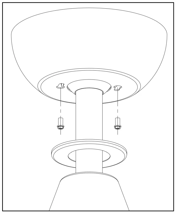
Install the Ceiling Canopy and Dress Ring
Step 1: Lift the ceiling canopy up and over the hanger bracket, lining the key slot in the ceiling canopy over the shoulder screw holes in the hanger bracket. Loosely install the two shoulder screws into the ceiling canopy and then rotate the ceiling canopy to lock into place.
Fully tighten the shoulder screws to lock the ceiling canopy in place.
Step 2: Raise the Dress Ring up the Downrod and center accordingly. The Dress Ring is held in place by magnets.
Install the base plate (non-light installation)
Step 1: Position the four clips located on the Base Plate to be in line with holes in the motor bottom, and then twist the Base Plate to lock into place.

(Optional) Install the Light Kit
Step 1: Remove the Light Kit Attachment Plate from within the LED Light Kit by twisting and lifting.

Step 2: Securely attach and tighten the Light Kit Attachment Plate to the bottom of the ceiling fan motor by routing the wires through the Attachment Plate and then lifting the Light Kit Attachment Plate and screwing onto the motor shaft, hand tightening only.

Step 3: Connect the 2-pin light plug coming from the Light Kit to the 2-pin light plug coming from the Fan Motor.
Step 4: Fit the LED Light Kit to the Attachment Plate, being careful to not pinch the wires, and by rotating clockwise to secure.

Operating the handset (transmitter)
*Down Light CCT Toggle:
To adjust the colour, turn Down Light On, then rapidly switch the Down Light
Off and back On.
Repeat this to toggle between the colours.

Learning / Pairing Setup
The handset and remote control receiver module are pre-programmed at the factory and do not normally require pairing. Should they not function when first installed, or you wish to control 2 fans using 1 handset, or you need to pair a replacement handset please follow the below procedure.
- Ensure that AC power is isolated (switched off) to the ceiling fan.
- Restore AC power to the fan. Within 30 seconds PRESS and HOLD the Fan Reverse/Forward button for 10 seconds.
- The remote control receiver module will beep to indicate the pairing process was successful.
Caring for and operating your remote control
Ensure the batteries are correctly installed in the hand piece. Please allow a moment between each switching operation. Please handle the transmitter with care, be sure not to drop or expose it to water, high humidity or place it too close to a heating element. Improper handling may result in malfunction and void the warranty. The remote control is operated by Radio Frequency so it isn’t necessary to point the unit at the ceiling fan.
Blade balancing
Whilst every precaution is taken at the factory to ensure your fan is of the highest quality, imbalance may occur. This may be due to slight irregularities in the blades or material densities. Further problems can be caused by deviating from these instructions.
The following procedure may help to rectify the situation.
- The hanger bracket must always be tight against the ceiling so that no movement can occur.
- Make sure that the downrod is firmly locked into the hanger ball on top of the fan. The locking screw should be securely tightened.
- Check all the blades are firmly tightened onto the motor.
- Changing over two adjacent blades – may correct any imbalance causing wobble.
- Please note that drop rod style of fans have a slight level of movement but this is not dangerous. Longer drop rods may amplify the amount of wobble.
Care and cleaning
The motor has permanently sealed bearings so no lubrication is necessary.
Periodic cleaning of your new fan is recommended (particularly the blades). The plated or painted surfaces of your fan have been sealed with a lacquer to minimize any discoloration or tarnishing. Therefore use a soft brush or lint free cloth to avoid scratching the surface.
Do not use water or chemicals when cleaning your fan as this could damage the surfaces of the casing and the blades and may create the possibility of an electric shock.
ThreeSixty Fans – Plain English Warranty Terms
SHOULD THERE BE ANY INSTALLATION ISSUES OR DEFECTS PLEASE IMMEDIATELY CALL OUR SUPPORT HELP LINE ON 1300 469 326 FOR ASSISTANCE AND ADVICE. DO NOT ATTEMPT TO UNINSTALL OR REMOVE THE PRODUCT FROM THE CEILING UNLESS SPECIFICALLY ADVISED TO BY THREESIXTY FANS AS THIS WILL CAUSE DELAYS DIAGNOSING AND RESOLVING THE ISSUE.
Our goods come with guarantees that cannot be excluded under the Australian Consumer Law. You are entitled to a refund or replacement for a major failure and for compensation for any other reasonably foreseeable loss or damage. You are also entitled to have the goods repaired or replaced if the goods fail to be of acceptable quality and the failure does not amount to a major failure.
Mechanical and Structural Components
Your Product is covered against mechanical and structural defects that prevent
it from working by a limited 36 month on-site warranty. This warranty covers
only the product itself and excludes workmanship or materials related to its
installation or any modifications. A major failure may be, for example, a
motor defect preventing a product from operating shortly after it was first
installed or if it was damaged while in the original packaging. If the product
stops working due to a mechanical or structural defect within the first 36
months we will repair or replace the product at our discretion.
Electronic Components
Your Product is covered against electronic defects that prevent it from
working by a limited 12 month on-site warranty. This warranty covers only the
electronics supplied with the product and excludes workmanship or materials
related to its installation or any modifications. A major failure may be, for
example, a power module that failed shortly after it was first installed or if
it was damaged while in the original packaging. If the product stops working
due to an electronic defect within the first 12 months we will repair or
replace the electronic part at our discretion.
Compensation for reasonably foreseeable loss
Compensation normally comprises us paying associated labour costs to replace
the defective product if it’s installed within a reasonable distance from our
repair agent. If beyond a reasonable distance (30km) you can arrange your own
electrician and we will compensate you for this up to a maximum of $115.50 inc
GST. Note, we do not pay extra for extended travelling time or additional
costs when the job requires a longer than average time to complete.
To prevent or limit costs you may incur for service calls, you must notify us of the intention to use your own contractor and not engage one until we have spoken to them (to arrange parts that may be required). If the problem is not a defect covered by our warranty terms you will have to pay all costs. To reduce cost and inconvenience for all involved we will do our best to diagnose the fault and supply parts before the contractor visits the site.
Eligibility for In-Home Service Calls
Hard wired electrical products must (by law) be installed by a licensed
electrician. To obtain in-home warranty service you must be able to provide a
copy of the installing electricians invoice or the Certificate of Compliance
given to you when the product was first wired up and tested. If you cannot
provide this information we limit our warranty to repair or replacement of the
product at our workshop and you will bear the costs of removal, shipping to us
and reinstallation. We will pay the freight to send the rectified unit back to
you.
Access to products
Products installed on ceilings 4m and above may require special access
equipment or WH&S measures. All costs for this equipment must be borne by the
site owner and the ceiling height given when booking a service call. If a
service agent chooses not to access a product installed at height due to WH&S
concerns the owner must remove and reinstall the product at their own expense.
Isolation Switches
Australian Standards require our instructions to state an isolation switch
must be fitted. This allows the product to be physically switched off in case
of faults or to prevent damage from surges, lightning, etc. Emergency
disconnection and/or remote control re-programming that can’t be performed due
to lack of an isolation switch is not covered by warranty.
Commencement
The warranty period begins from date of purchase and in-home warranty service
is available only at the site of original installation. If the product is
installed as part of a project or development the warranty period commences
when the product was delivered to the site.
Damage
Damage from Force Majeure, electrical surges, wind, rain, lightning, power
grid fluctuations, water ingress, condensation or use with incompatible power
sources will not be rectified under warranty. Likewise solid state or dimmer
type speed controls may damage ceiling fans or cause them to make unusual
noises. Genuine parts and advice are available through our online and
telephone support services.
Cosmetic defects
Carefully inspect your product prior to installation and notify us as soon as
possible if there are cosmetic defects. Cosmetic defects are generally not
covered by warranty unless present when the product is initially unpacked.
Damage from being struck by objects or not being kept clean is not covered by
warranty.
Corrosion
Deterioration of finishes, including rusting, pitting, corrosion, fading,
tarnishing or peeling is not covered by warranty beyond six months. Products
specified as corrosion resistant or made from Stainless Steel are not
corrosion proof and will discolour or deteriorate if not cleaned. As a guide,
maintain your product as you would your kitchen appliances (clean every 3
months).
Noise
Signals sent through the power grid by the electricity supplier may cause
intermittent noises in your product. These noises are not the result of a
fault and filters to reduce this noise may be available at additional expense.
Clicking, ticking and creaking noises from fans are usually caused by the mounting bracket not being correctly attached or when blades screws are loose. Only use the hardware provided to install ceiling fans. If the mounting bracket is attached using counter-sunk screws it will work loose and cause unwanted noise and movement in your fan. Wooden bladed fans may need their blade screws periodically tightened. Unless a product is defective noise will not be rectified under warranty.
Wobbling
Wobbling is generally not caused by a defective fan but by air currents in the
room. After a fan has been running for a long period it will cause air
currents to form and, depending on the shape of the room and its furnishings,
the air returning to the fan may be uneven.
Improper mounting will also cause a fan to wobble. Every mounting bracket screw must be secured to solid materials in the ceiling. Metal C section rafters may need to be doubled to form a box section to prevent flexing. Foam sandwich ceiling panels will require reinforcing to stop flexing. Unless a product is defective wobbling will not be rectified under warranty.
Airflow
The amount of airflow produced by a fan is dependent on where it’s installed
because room shape, mounting height and furnishings will affect the perceived
air movement. A product is deemed to be functioning normally if it is running
within 15% of the specified RPM when installed.
Customer Support
ThreeSixty Fans Support can be contacted by calling 1300 469 326, visiting our website at https://360fans.com.au or emailing our team at support@360fans.com.au

References
Read User Manual Online (PDF format)
Read User Manual Online (PDF format) >>