Gehirn ENTERPRISES EuroWasp 12HP Euro Rack Edition Effect Pedal Instruction Manual
- June 12, 2024
- Gehirn ENTERPRISES
Table of Contents
 NoisWasp 12HP EURO RACK EDITION
DIY KIT ASSEMBLY INSTRUCTIONS
PARTS LIST & BILL OF MATERIALS
PCB’s
1x Faceplate PCB
1x Component PCB
Hardware
3x DIP8 Socket
1x Header 2×5 IDC
4x SPDT On/On switch – 2MS1T2B2M2RE
4x 3.5mm PCB mount Jacks
1x Packet of solder
Potentiometers and Knobs
| 2x 1k | 9mm PCB Linear |
|---|---|
| 2x 10k | 9mm PCB Linear |
| 1x 100k | 9mm PCB Linear |
| 3x 1M | 9mm PCB Linear |
1x Yellow 1900H knob
7x Black 1900H knob
Semiconductors
1x 2N3904 Transistor
1x LM78L09 Voltage Regulator
2x 1N914 Diodes
1x TL062 Op-Amp
2x TL072 Op-Amp
1 x LEDS PACKET
1x 3mm red LED
1x 3mm white LED
1x 3mm blue LED
1x 3mm dual red/green LED
1x OPTO PACKET
1x square red LED
1x square green LED
2x LDR light dependent resistor
1x 5mm heatshrink
Capacitors
| 2x 10nF | 50V MLCC |
|---|---|
| 2x 100nF | 50V MLCC |
| 3x 1uF | 50V MKT |
| 3x 1uF | 50V electrolytic |
| 1x 10uF | 25V electrolytic |
| 1x 100uF | 16V electrolytic |
Resistors
| 1x 220R | 1/8W 1% Metal film |
|---|---|
| 5x 1k | 1/8W 1% Metal film |
| 4x 4k7 | 1/8W 1% Metal film |
| 6x 10k | 1/8W 1% Metal film |
| 2x 15k | 1/8W 1% Metal film |
| 1x 47k | 1/8W 1% Metal film |
| 4x 100k | 1/8W 1% Metal film |
| 2x 220k | 1/8W 1% Metal film |
| 1x 470k | 1/8W 1% Metal film |
| 1x 1M | 1/8W 1% Metal film |
If any parts are missing or damaged please contact
gehirnenterprises@outlook.com or
0435472073 for free replacements.
Tools required for kit
Soldering Iron, Cutters, Pliers, 10mm spanner or socket, small flat blade
screwdriver, heat gun, rubber bands.
Assembly Procedure
-
PCB Check
Check Component PCB is clean and undamaged. There is a small notch filed in the top Right of the PCB which is meant to be there. If the PCB has become dirty, clean with Isopropyl Alcohol or Mentholated Spirits before soldering.
-
Install Resistors and 1N914 Diodes
It is easiest to build the PCB from the lowest height components to the tallest ones. The resistors and diodes have the shortest height. Resistors can be installed in any orientation, but the diodes are polarized, so the black stripeon the diode must face the same way as the white stripe on the PCB. Solder them in place and trim the leads.
-
Install MLCC Capacitors
The 10nF and 100nF MLCC capacitors are installed next.
-
Install DIP 8 sockets
IMPORTANT!!! The DIP8 sockets and IC’s on this PCB face downward. Make sure you check the orientation of the sockets (and IC’s) when you install them.
Solder the DIP8 sockets into place.Make sure the notch on the socketaligns with the notch on the PCB.
Do not install the TL072 and TL062IC’s yet.
-
Install 78L09, 2N3904 and electrolytic capacitors.
Install the 1uF capacitors lying down. They are a bit too tall for the gap between the panel and PCB but room has been left for this. The other components can be installed standing up.
-
Install OPTO
Install square LEDs from OPTO packet in LED5 and LED 6 positions. Long legs go to the flat side of the LED next to the text. Red LED goes to LED6, and Green LED to LED5.
Next cut two pieces of heatshrink to about the same height as the LED. Cut a small slit in the side of each one. This is for the LDR to poke through. Bend the legs of the LDR 90 deg and install into PCB so the LDR is touching the LED, and the heatskrink wraps around both parts. Heat the heatshrink with a heat gun so the LRD is held firmly in place.
If you don’t have a heatgun a lighter can be used but be EXTREMELY careful not to melt anything that shouldn’t be melted.
-
Install 1uF MKT capacitors
Solder MKT capacitors onto PCB, trim leads. -
Install IC’s
Install TL062 and TL072 IC’s in their sockets. Make sure they are in the correct orientation and the dot or notch is pointing down. IC’s are fairly interchangeable and many DIP8 Op-Amps could be used (i.e 4558) but best results come from the standard IC’s. -
Install switches
Install switches onto PCB. They are tricky little bastards. Trim leads on PRCLP and PSTCLP switches before soldering them in so the IDC connector can be soldered in flush later. PRCLP hangs off the PCB. The reason for this is that PCB’s under 100mm long are a lot cheaper.
-
Install 3.5mm Jacks
Remove nuts from 3.5mm jacks and sit inplace. Use PCB panel to align Jacks with switches. A rubber band can assist with holding it in place. Solder into place and remove PCB panel.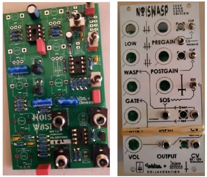
-
Install Potentiometers
Remove nuts and washers from potentiometers, trim alignment notches if present and sit the pots in place. Use PCB panel to align Jacks with Switches. A rubber band can assist with holding everything together. Align the pots so they are as straight as possible and are contacting both PCB’s. Solder into place and remove PCB panel.
-
Install 2×5 IDC Connector
Install 2×5 IDC connector on the back of the PCB, so the notch faces the inside of the PCB -
Install LEDs
Install LEDs into PCB but do not solder into place. Fit Panel PCB and install nuts and washers from the Potentiometers and Jacks. Then align LED’s to protrude the desired amount from the faceplate. Trim leads.
-
Install Knobs
Turn all potentiometers fully counter clockwise. Align knob pointer with mark on Faceplate PCB and tighten screw, then proceed to the next one. Yellow knob goes on the wasp control. It’s easiest to do the left row first. -
Verification and testing
Apply power to module. Hopefully no pops, bangs or magic smoke comes out 🙂
Apply +12V to CV input, LED should illuminate RED, apply -12V and it should go GREEN. If the reverse happens the LED is in backwards (sometimes can they vary from batch to batch, it’s very annoying). To fix this, de-solder it and install in the opposite direction. Apply 12V to BiDirectional CV input/Output. LED should illuminate BLUE.
This is a very unpredictable module. If there is no audio output it might still be OK. Try turning a few knobs and see if it starts to output audio. You probably won’t get an output if LOW is all the way up, or VOL and WASP are all the way down.
The RED, WHITE and BLUE LED’s won’t blink in certain settings. They only illuminate in the most intense oscillations. Put the clipping switches up and crank up the pre gain and post gain will help with this. The WHITE LED often isn’t as bright as the RED, this is normal.
Plug into your amp / monitoring / front of house / PA etc and play at the volume of 50 billion nuclear explosions. If the police arrive with a noise complaint it’s working as intended.
Questions, comments, missing components, fault finding, service, repairs, sales and all other inquiries can be sent to gehirnenterprises@outlook.com
Thank you for building a NoisWasp !!!
Regards, Brendan
Documents / Resources
|
Gehirn ENTERPRISES EuroWasp 12HP Euro Rack Edition Effect
Pedal
[pdf] Instruction Manual
EuroWasp 12HP Euro Rack Edition Effect Pedal, EuroWasp 12HP, Euro Rack Edition
Effect Pedal, Effect Pedal, Pedal
---|---
Read User Manual Online (PDF format)
Read User Manual Online (PDF format) >>