B17 Pro-Cut On Car Brake Lathes User Guide
- June 9, 2024
- B17
Table of Contents
QUICK START GUIDE
P · 800.543.6618
F · 603.298.8404
info@procutusa.com
www.procutusa.com
Pro-Cut On Car Brake Lathes
B17 SET-UP FOR STANDARD PACKAGE
Follow Steps and Scan QR Codes for Corresponding Videos.


5. Remove 5 bolts holding lathe to pallet. Install 3 lifting eye bolts and attach the 49-4020 lifting chain. The 2 short lengths attach to the top eye bolts, and the long chain secures to lower eye bolt to keep the lathe level during lifting.

Insert Lift Eyes (5A / 5B). Add a rag behind lift chain to pad ways.
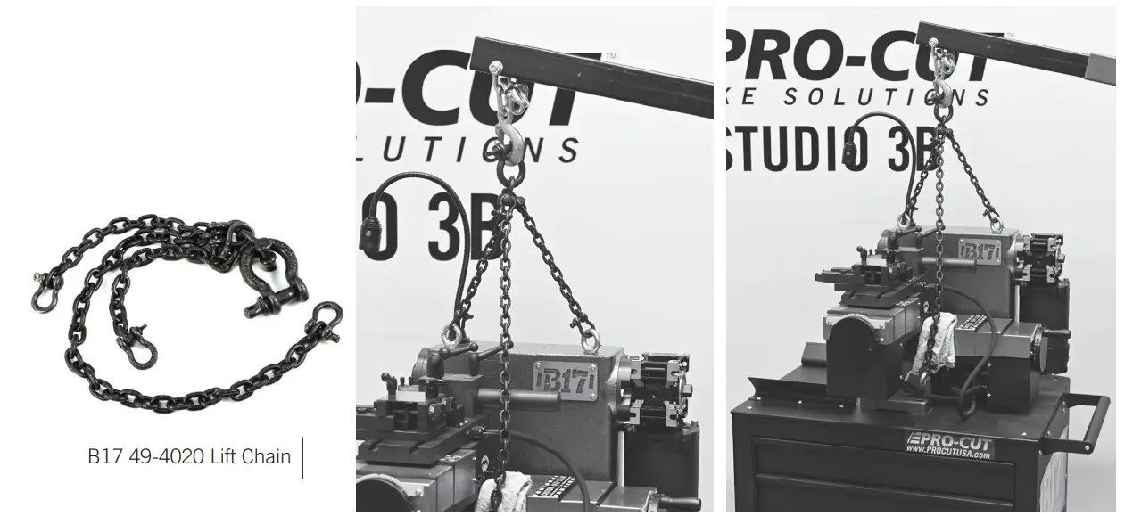
6. Lift the B17, using a 2 ton engine hoist and 2 people. Before lifting be certain none of the chains are arranged in a way that will cause damage to the lathe.

7. Roll the mobile cart under the lift- ed B17 and line up the bolt holes on
the lathe to the top of the mobile cart. Lower the lathe slowly until 1/4” off
cart top and start screws by hand. Land the lathe and tighten screws securely.
8. Remove the 3 screws w/washers already installed on the top center of the
lathe body. Install command module with the 3 screws. Find the 2 connectors
for rear of command and carefully plug them into their corresponding port on
the back of the command module. Be certain to use foam gasket provided with
multi-pin connector.

*WARNING: DO NOT PLUG IN COMMAND MODULE CONNECTORS WHEN AC POWER IS PLUGGED IN.
9. Find and install the handles for the disc and drum axis cranks.

10. Remove 4 bolts that attach draw bar nut end cover (5mm hex)
11. Check both disc and drum axis ways for any looseness by trying to wiggle
each of the gear boxes side to side and up and down. Adjust gib ways as
necessary to achieve a snug gib with smooth action when either crank handle is
turned.

11. (Continued) Oil the ways with 50-376 way oil provided.
12. Carefully remove arbor and drawbar from the packaging. Using a clean cloth, wipe the tapered end of the arbor and the receiver hole on the lathe, and inspect for any burrs or shipping damage. Use ScotchBrite to clean the tapered end if needed.

13. Screw the drawbar into the end of the arbor until it is tight. Carefully send the drawbar through the lathe until the threaded section of the drawbar protrudes through the other end of the lathe and the tapered end is fully landed. If there is a match mark, be certain to reference that point.

14. Use an open end wrench on the flats at the end of the spindle to hold the
spindle from moving. Then use a torque wrench and torque the 36-4005 drawbar
nut to 30 lb-ft.
15. Use a roller tip dial indicator to measure the lateral motion of the
arbor as close to threads of arbor as is possible. The roller tip should be
perpendicular to the arbor shaft and centered. If the lateral run-out (LRO) is
above .001”, loosen drawbar nut and change arbor position until desired run-
out is achieved and re-torque to 30 lb- ft.

16. Once the arbor LRO is correct, reposition your dial indicator tip to the
arbor base. Spin the spindle on slow speed and observe reading. There should
be .0005” or less at the arbor base. If run-out is excessive, clean base face
with Scotch-Brite or fine sandpaper until .0005” or less is achieved. Contact
Pro-Cut’s service dept if you are unable to reduce LRO to within
specification: 1-800-543-6618 ext. 2
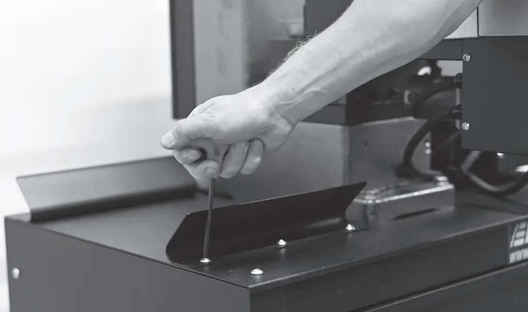
17. Install the 50-4745 chip guard by first screwing in threaded insert into
hole to the left of the command module. Then screw plastic base piece down
with bolt. Click the plastic joints together to mount the chip guard to the
base

18. Install chip tray brackets using 4 bolts provided and set chip tray in
between the brackets.
19. Open the rest of the loose parts and arrange in drawers – accessories in
top drawer, black adapters in foam in middle drawer, and Quick-Chucks or other
accessories in bottom drawer

20. Perform pre-test: Power up the lathe and check that all functions are
working on the command module. While doing that record DRO readings, and be
certain the maintenance alert is set to the customer’s preference. Check that
the arbor light is working properly when Quick-Pivot plate is switched between
rotor and drum modes.
21. Chuck a rotor up to the machine and make a pass to confirm cut quality
and LRO.

MAINTENANCE SCHEDULE
BRUSH CLEAN DAILY
- Empty Chip Tray
- Arbor
- Gearbox Rails
- Slide Plate
- Cutting Head
INSPECT WEEKLY
- Power Cord
- Cutting Tips/Screws
- Cutting Head Arm Adjustment
- Gear Box Ways – Lubricate
MONTLY MAINTENANCE
- Drawer Slides – Inspect
- Cart Wheels / Locks – Inspect
- Cones and Adapters – Inspect
- Gear Box Way Covers – Inspect
- Feed Screw / Lead Nut – Lubricate
- Arbor Position – Verify with Dial Indicator
- Gib Adjustment – Both Disc and Drum
YEARLY
- Contact Pro-Cut Service Department
QUESTIONS?
- Contact the Pro-Cut Service Department at 1-800-543-6618 / Prompt #2
NOTES
Pro-Cut International, LLC
10 Technology Drive #4
West Lebanon, NH 03784
P. 800.543.6618 / 603.298.5200
F. 603.298.8404
E. info@procutusa.com
Global inquiries please see:
www.procutusa.com
© PRO-CUT INTERNATIONAL, LLC
R 12.2022
https://youtu.be/ZoPKlS37D6U
References
Read User Manual Online (PDF format)
Read User Manual Online (PDF format) >>