VARIMETER RN5897 Insulation Monitor Instruction Manual
- June 14, 2024
- VARIMETER
Table of Contents

![]() Monitoring Technique
VARIMETER IMD
Monitoring Technique
VARIMETER IMD
Insulation monitor
RN 5897/300 Translation of
the original instructions
Translation of
the original instructions
0274214
Product Description
The insulation monitor RN 5897/300 of the VARIMETER IMD familyprovides best and up to date insulation monitoring of modern IT systemsin an optimum and state of the art way fulfilling the relevant standards.The device can be used in the most flexible way for AC, DC and AC/DCsystems. The adjustment of the setting values is simple and user friendlydone on 3 rotary switches on the front of the device. Via multicolor LED thedevice status is indicated easy to read. With a sealable transparent coverthe device is protectet against manipulation.
Circuit Diagram

Connection Terminals
| Terminal designation | Signal description |
|---|---|
| A1(+), A2 | Auxiliarx voltage AC or DC |
| L(+), L(-) | Connection for measuring ciruit |
| PE1, PE2 | Connection for protective conductor |
| X1, X2 | Control input (combined external Test- and Reset-input) |
| 11, 12, 14 | Alarm signal relay K1 (1 changeover contact) |
| 21, 22, 24 | Prewarning signal relay K2 (1 changeover contact) |
Your Advantages
- For mobile generator sets according to DIN VDE 0100-551
- Preventive fire and system protection
- Detection of symmetric and asymmetric insulation faults
- Universal application in non-earthed AC, DC, AC/DC networks uptomax.300V
- Easy adjustment of response values and setting parameter via rotational switch
- Suitable for large leakage capacitances up to 30 µF
- Monitoring also with voltage-free mains
- Measuring circuit L(+)/L(-) with broken wire detection (can be switched off)
- Protective conductor PE1/PE2 with broken wire detection (can’t be switched off)
- No additional coupling device required
Features
- Insulation monitoring according to IEC/EN 61557-8
- 2 separate adjustable response thresholds (using e.g. for pre-Alarm and Alarm)
- Setting range of 1st response value (Pre-Alarm): 20 kΩ … 1 MΩ
- Setting range of 2nd response value (Alarm): 10 kΩ … 250 kΩ
- 2 changeover contacts für insulation failures-Pre-Alarm and -Alarm
- Energized or de-energized on trip can be selected for indicator relay
- LED for status indication
- Automatic and manual device self-test
- Alarm storage selectable
- Protection against manipulation by sealable transparent cover
- External control input for combined Test-/Reset-button
- 3 wide voltage input for auxiliary voltage
- Width 52.5 mm
Approvals and Markings

Applications
Insulation monitoring of:
- Non-earthed AC, DC, AC/DC networks
- UPS systems
- Networks with frequency inverters
- Battery networks
- Networks with direct current drives
- Hybrid and battery-powered vehicles
- Mobile generator sets
Function
The device is supplied with DC auxiliary voltage via terminals A1(+) / A2.
Switching on the auxiliary voltage (Power-On) is followed by an internal self-
test for 12 sec (see „Device test functions“). The test process is visible in
the status LED. After this, measurement of the insulation resistance in the
measuring circuits begins and the the colour of the status LED changes to
green.
Measuring circuit
(Insulation measurement between terminals L(+) / L(-) and PE1/PE2) The
terminals L(+) and L(-) are connected directly to the voltage system to be
monitored. A broken wire detection creates a fault signal if there is no low-
ohmic connection between both terminals.
The type of network (AC, DC, 3NAC) has to be selected.
Also the terminals PE1 and PE2 have to be connected with 2 separate wires to
the protective earth. An interruption of a wire also causes a fault signal
(see section ”Behavior on faulty connection”). The monitoring of the PE
connection cannot be de-activated.
To measure the insulation resistance an active measuring voltage with changing
polarity is connected between L(+)/L(-) and PE1/PE2.
At the end of a measuring cycle the actual insulation resistance is produced
and indicated. The relays for alarm K1 and pre-alarm K2 switch when dropping
under the adjusted response values. In addition the LED changes to orange
color on pre-alarm or to red color on alarm.
Manual reset of fault message
The rotary switch “UN” is devided in 2 sections. So additional to the type of
voltage system also manual or autoreset can be selected. (Alarm storing:
manual reset, no alarm storing: auto reset).
If manual reset is activated the insulation fault signals of the measuring
circuit are stored when dropping under the adjusted response values also if
the insulation resistance goes back to healthy state. Pressing the „Reset“
button on the front side for 2 s, the alarm signal are reset if the actual
insulation resistance is in healthy state.
Indicator relay for insulation fault signal
For the indicator relays K1 (contacts 11-12-14, for alarm) and K2 (contacts
21-22-24, for pre-alarm) the function energized on trip or de-energized on
trip can be set via pre-alarm rotational switch “RpA ” when the insulation
resistance drops below the adjusted response value.
Broken wire detection
As described in section “Measuring circut”, the measuring circuits L(+)/L(-)
and the protective conductors PE1/PE2 are constantly monitored for wire breaks
– not only at Power-On or a manual or occasional automatic test. The response
time of monitoring is only a few seconds. Broken wire detection between L(+)
and L(-) is performed via coupled alternating voltage. This alternating
voltage is short-circuited if the terminals are connected to the connected
mains at low-resistance. The device detects that the mains to be monitored is
properly connected.
Since this broken wire detection is carried out with alternating voltage,
large capacitances should be avoided between L(+) and L(-), since the
capacitive reactance of these capacitances also short-circuits this
alternating voltage. The device would no longer detect a connection fault on
L(+)/L(-).
Especially parallel lines should be avoided over larger distances.
If larger capacitances between L(+)/L(-) cannot be avoided or if the coupled
alternating voltage interferes with the system, the broken wire detection can
be de-activated using alarm rotary switch “RA “. Monitoring deactivated or
continuous monitoring (every 2 minutes for 10 sec) are the possible options.
If the broken wire detection on L(+)/L(-) is de-activated no AC voltage is
injected.
The broken wire detection on PE1/PE2 cannot be de-activated.
Device test functions
Principally, 2 different test functions are implemented: The “self-test” and
the “expanded test”:
The self-test of the device is performed automatically after Power-On and
every full operating hours. It can also be triggered manually at any time by
pressing the “Test” button at the device front for 2 sec.
With the self-test, contrary to the expanded test, the status of the Indicator
relays is not affected; the sequence is as follows:
The self-test is indicated via LED with orange flash code 1. For approx. 5 s
to negative test phase. Within these 5 s the internal measuring circuit is
checked for failures. Then the measuring pulse is switched for approx. 5 s to
positive test phase and more internal tests take place. If no failures turned
up and had been recognized, the measurement continuous. The extended test
procedure is started when during or at the end of the above described self-
test (12 s) the test button is pressed again for 2 s. The sequence is similar
to the self-test (2 measuring phases of 5 s each) but in addition the output
relays go in alarm stated. The LED shows orange flash code 2. The test phases
of the extended test will be repeated continuously. The extended test can be
finished after the first complete sequence (approx. 10 sec) by pressing the
“reset” button for 2 seconds. The device starts the insulation monitoring
again.
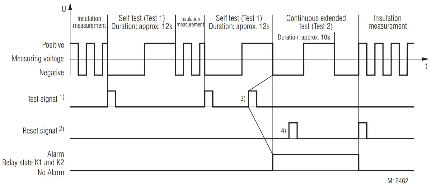
- Test signal: Button Test > 2 s or X1/X2 < 3 s
2) Reset signal: Button Reset > 2 s or X1/X2 > 3 s - To initiate the extended test (Test 2) the test signal must be operated within the self test (Test 1) again.
- The reset signal has here no function, as the first complete sequence of extended test (Test 2) is not finished.
Behaviour with internal device faults
If internal device faults were detected during the test function, the LED
flashes continuously red. The indicator relays K1 and K2 switch to the alarm
state.
Behavior on faulty connection
When detecting broken wire on terminals L(+)/L(-), the measurement is
disabled. The reaction time could be up to 2 min. The monitoring relays K1 and
K2 go in alarm state, the LED indicates the red flash code 1. After removing
the interruption the fault is automatically reset (max. reaction time up to 2
min) and the measurement of the insulation resistance is continued. Stored
alarm values remain stored. An interruption of the protective earth
connections PE1/PE2 causes the same reaction as interrupting the measuring
circuit, only the LED indicate the red flash code 2.
External control input
To terminals X1/X2 an external combined Test-/Reset button can be connected.
If the terminals X1/X2 are bridged for approx. 1 s the test mode is started.
This has the same function as pressing the internal test button. When bridging
X1/X2 for > 3 s, a stored alarm will be reset. This has the same function as
pressing the internal reset button.
Programming/setting of parameters/set-up of the insulation monitor
All setting are done with 3 rotary switches on the front of the unit. To avoid
unauthorized manipulation of the settings, all 3 switches are located behind a
sealable transparent cover. The first rotary switch “RA ” sets the response
value for alarm. In addition it is divided in 2 sections. If the setting
position is in the first section the broken wire detection is permanent
enabled, if the setting position is in the second section the broken wire
detection is permanent disabled. The second rotary switch “RpA ” sets the
response value for pre-alarm. In addition it is also divided in 2 sections. If
the setting position is in the first section, the relay output function is de-
energized on trip, if the setting position is in the second section, the relay
output function is energized on trip.
The third rotary switch “UN” selects the type of network connection. It is
also divided in 2 sections. If the setting position is in the first section,
the unit is on auto reset, if the setting position is in the second section,
the unit is on manual reset.
New settings are accepted without restart of the device.
Function Diagram

Flashing Codes Status LED
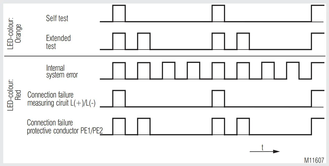
Indicators

The operational status of the device is indicated on a 3-colour LED:
| Off: | No auxiliary voltage connected |
|---|---|
| Green: | Normal operation (Insulation resistance in healthy state) |
| Red: | Alarm (measured value below alarm response value) |
| Orange: | Warning (measured value below pre-alarm response value) |
| Orange flashing: | Orange flashing: Test mode procedure (see flashing code |
diagramm)
Red flashing:| Failure code (see flashing code diagramm)
Flash code orange Status-LED| Description
---|---
1| Selftest
(measuring circuit, measuring voltage, internal tests)
2| Advanced Test
(additional control of indicator relays)
Error Indication
| Flash code red Status-LED | Failure cause | Failure recovery |
|---|---|---|
| 1 | Broken wire detection on L(+)/L(-). | Check measuring circuit L(+) and L (-) |
| 2 | Broken wire detection on PE1/PE2. | Check protective earth connections PE1 |
and PE2
Continously flashing| Internal failure detected in test mode| Press test
button again or restart the unit by interrupting the auxiliary supply
temporarily. If the fault remains permanent, send device back to manufacturer
for examination.
Continously flashing| Faulty calibration values detected in device memory.|
Send device back to manufacturer for recalobration and examination.
Notes
WARNING
Risk of electrocution!
Danger to life or risk of serious injuries.
- Disconnect the system and device from the power supply and ensure they remain disconnected during electrical installation.
- The terminals of the control input X1-X2 have no galvanic separation to the measuring circuit L(+) and L(-) and are electrically connected together, therefore they have to be controlled by volt free contacts or bridge. These contacts ore bridges must provide a sufficient separation depending on the mains voltage on L(+)-L(-).
- Please do not connect external voltage to terminals X1/X2. The control must only be made by bridging X1 and X2.
Attention!
- Before checking insulation and voltage, disconnect the monitoring device RN 5897 from the power source!
- In one voltage system only one insulation monitor can be used. This has to be observed when interconnecting two separate systems..
- Device terminals PE1 and PE2 must always be connected via separate lines to different terminal points of the protective-conductor system.
- The device must not be operated without PE1/PE2 connection!
Attention!
- The main measuring circuit can be connected with its terminals L(+) and L(-) both to the DC and also AC side of a mixed network; it is done most practically where the primary incoming power supply takes place e.g. battery networks with connected inverters on the DC side, with Generators/Transformers with connected Rectifiers or inverters on the AC-side. To monitor a 3NAC system the device can be connected single pole, (L(+) and L(-) are bridged, to the neutral of the 3p4w system. The 3 phases have a low-ohmic (approx. 3 – 5 Ohm) connection via the transformer windings so also insulation failures of the not directly connected phases are detected. Via the rotational switch „UN“ the correct type of network needs to be selected (see „Connection Examples“).
- If a monitored AC system includes galvanically connected DC circuits (e.g. via a rectifier), an insulation failure on the DC side can only be detected correctly, when a current of min 10 mA can flow via the semiconductor connections.
- If a monitored DC system includes galvanically connected AC circuits (e.g. via an inverter), an insulation failure on the AC side can only be detected correctly, when a current of min 10 mA can flow via the semiconductor connections.
Technical Data
Measuring ciruit L(+) / L(-) to PE1 / PE2
| Nominal voltage UN: | AC / DC 0 … 230 V |
|---|---|
| Max. voltage range UN: | AC / DC 0 … 300 V |
| Frequency range: | DC or 40 … 1000 Hz |
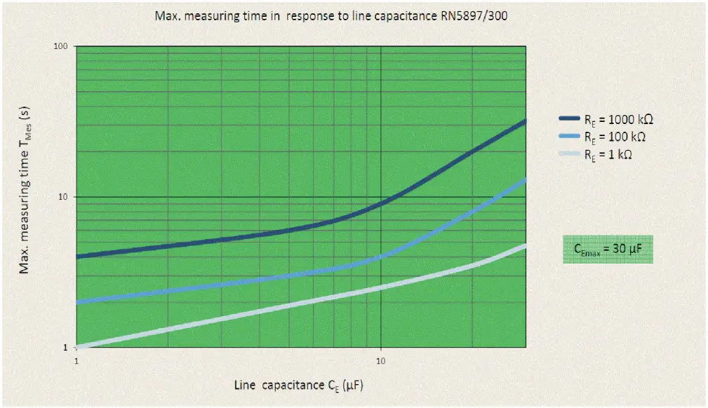
| Max. line capacitance: | 30 µF |
| Internal resistance (AC / DC): | > 120 kΩ |
| Measuring voltage: | Approx. ± 90 V |
| Max. mesured current (RE= 0): | < 0.80 mA |
| Response inaccuracy: | ± 15 % ± 1.5 kΩ IEC 61557-8 |
| Response value hysteresis: | Approx. + 25 %; min. + 1 kΩ |
On delay
at CE = 1µF,
RE of ∞ to 0.5 * response value:| ≤ 1 s (at setting 3N AC)
< 5 s (at setting AC, DC)
---|---
Measuring time:
at CE = 1 … 30 µF,
RE from ∞ to 1000 kΩ,
RE from ∞ to 100 kΩ,
RE from ∞ to 1 kΩ: See characteristics
Response values:
Pre-warning („RpA“):
| kΩ: | 20 | 50 | 100 | 500 | 1000 |
|---|
Alarm („RA“)
| kΩ: | 10 | 20 | 50 | 100 | 250 |
|---|
Each adjustable via rotational switches
| Response value broken wire detection L(+)/L(-): | > Approx. 30 kΩ |
|---|---|
| Response value broken wire detection PE1/PE2: | > Approx. 0.5 kΩ |
Auxiliary voltage input A1(+)/A2
| Nom. Voltage | Voltage range | Frequency range |
|---|---|---|
| AC/DC 24 … 60 V | AC 19 … 68 V | 45 … 400 Hz; DC 48 % W*) |
| DC 16 … 96 V | W*) ≤5% | |
| AC/DC 85 … 230 V | AC 68 … 276 V | 45 … 400 Hz; DC 48 % W*) |
| DC 67 … 300 V | W*) ≤5% | |
| DC 12 … 24 V | DC9.6…30V | W*) ≤5% |
*)W=Permitted residual ripple of auxiliary supply
Nominal consumption:****
| DC 24 V, 48 V: | Max. 3 W |
|---|---|
| AC 230 V: | Max. 3.5 VA |
Control input X1/X2 for external kombinierte Test-/Reset-Taste
| Current flow: | Approx. 3 mA |
|---|---|
| No-load operation voltage X1 to X2: | Approx. 12 V |
| Permissible wire length: | < 50 m |
| Activation time for test signal: | Approx. 1 s |
| Activation time for reset signal: | > 3 s |
Outputs
Indicator contact:| 2 x 1 changeover contact for Alarm (K1) and Pre-Alarm (K2)
energized or de-energized on trip (programmable)
---|---
Thermal current Ith:| Max. 4 A (see also Temperature range Operation)
Switching capacity to AC 15:
| NO contact: | 5 A / AC 230 V | IEC/EN 60947-5-1 |
|---|---|---|
| NC contact: | 2 A / AC 230 V | IEC/EN 60947-5-1 |
| To DC 13: | 2 A / DC 24 V | IEC/EN 60947-5-1 |
Electrical life
| at 5 A, AC 230 V: | 1 x 10⁵ switching cycles |
|---|
Short circuit strength
| Short circuit strength max. fuse rating: | 4 A gG / gL | IEC/EN 60947-5-1 |
|---|---|---|
| Mechanical life: | 50 x 106 switching cycles |
General Data
| Operating mode: | Continuous operation |
|---|
Temperature range
Operation:
| Auxiliary voltage DC 12 … 24 V, AC/DC 24 … 60 V: | – 40 … + 70 °C |
|---|---|
| Auxiliary voltage AC/DC 85 … 230 V: | – 40 … + 60 °C |
– 40 … + 70 °C
(device mounted with min. 1 cm distance to adjacent devices or device with
max. 2 x 0.5 A contact current)
Storage:| – 40 … + 70 °C
Altitude:| ≤ 2000 m
IEC 60664-1
Clearance and creepage distances
| Rated insulation voltage: | 300 V |
|---|---|
| Overvoltage category: | III |
| Rated impuls voltage /pollution degree: | IEC 60664-1 |
Measuring circuit L(+)/L(-) to auxiliary voltage A1(+)/A2 and indicator relay
contacts K1, K2:| 4 kV / 2
Auxiliary voltage A1(+)/A2 to indicator relay contacts K1, K2:| 4 kV / 2
Indicator relay contact K1 to indicator relay contacts K2:| 4 kV / 2
Insulation test voltage Routine test:| AC 2.5 kV; 1 s
EMC
| Electrostatic discharge (ESD): | 8 kV (air) | IEC/EN 61000-4-2 |
|---|
HF irradiation:
| 80 MHz … 1 GHz: | 20 V / m | IEC/EN 61000-4-3 |
|---|---|---|
| 1 GHz … 2.7 GHz: | 10 V / m | IEC/EN 61000-4-3 |
| Fast transients: | 2 kV | IEC/EN 61000-4-4 |
| Surge voltage between wires for power supply: | 1 kV | IEC/EN 61000-4-5 |
| Between wire and ground: | 2 kV | IEC/EN 61000-4-5 |
| HF-wire guided: | 20 V | IEC/EN 61000-4-6 |
| Interference suppression: | Limit value classe B | EN 55011 |
Degree of protection
Housing:| IP 30 (not sealed)
IP 40 (sealed with seal wire 50/30)
The unit must be disconnected from the power supply before the seal is
applied| IEC/EN 60529
IEC/EN 60529
---|---|---
Terminals:| IP 20| IEC/EN 60529
Housing:| Thermpolastic with V0 behaviour according to UL subject 94
Vibration resistance:| Amplitude 0.35 mm,
Frequency 10 … 55 Hz, IEC/EN 60068-2-6
Frequency 2 … 13.2 Hz, 13.2 … 100 Hz, acceleration ± 0.7 gn
IEC/EN 60068-2-6
Shock resistance:| 10 gn / 11 ms, 3 pulses| IEC/EN 60068-2-27
Climate resistance:| 40 / 070 / 04| IEC/EN 60068-1
Terminal designation:| EN 50005| DIN 46228-1/-2/-3/-4
Wire connection
Cross section:| 0.5 … 4 mm² (AWG 20 – 10) solid or
0.5 … 4 mm² (AWG 20 – 10) stranded wire without ferrules
0.5 … 2.5 mm² (AWG 20 – 10) stranded wire with ferrules
---|---
Stripping length:| 6.5 mm
Max. fixing torque:| 0.5 Nm
Wire fixing:| Box terminal with cross recess screw
Mounting:| DIN rail
IEC/EN 60715
Weight:| Approx. 200 g
Dimensions
| Width x height x depth: | 52.2 x 90 x 71 mm |
|---|---|
| Vibration and shock resistance: | Category 1, Class B |
IEC/EN 61373
Service temperature classes:| OT1, OT2 compliant
Protective coating of the PCB:| No
UL-Data
Temperature range:
Operation:| -30 … + 60 °C
---|---
Switching capacity:| Pilot duty C300, R300
5A 250Vac
2A 30Vdc
Wire connection:| 60 °C / 75 °C copper conductors only Torque 0.5 Nm
Test specification:| ANSI/UL 60947-1, 5th Edition
ANSI/UL 60947-5-1, 3rd Edition
CAN/CSA-C22.2 No. 60947-1-13, 2nd Edition
CAN/CSA-C22.2 No. 60947-5-1-14, 1st Edition
Technical data that is not stated in the UL-Data, can be found in the
technical data section.
CCC-Data
Switching capacity
To AC 15
| NO contact: | 3 A / AC 230 V |
|---|---|
| NC contact: | 1 A / AC 230 V |
Technical data that is not stated in the CCC-Data, can be found in the
technical data section.
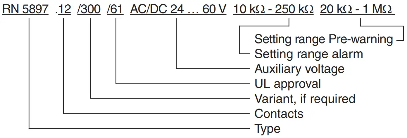
Standard Types
| RN 5897.12/300/61 | DC 12 … 24 V |
|---|---|
| Article number: | 67252 |
| Auxiliary voltage: | DC 12 … 24 V |
| RN 5897.12/300/61 | AC/DC 24 … 60 V |
| Article number: | 66942 |
| Auxiliary voltage: | AC/DC 24 … 60 V |
| RN 5897.12/300/61 | AC/DC 85 … 230 V |
| Article number: | 66943 |
| Auxiliary voltage: | AC/DC 85 … 230 V |
| Outputs: | 1 changeover contact for pre-warning |
1 changeover contact for alarm
Setting range pre-warning:| 20 kΩ … 1 MΩ
Setting range alarm:| 10 kΩ … 250 kΩ
Max. line capacitance:| 30 µF
Energized or de-energized on trip|
Selection of type of network|
Width:| 52.5 mm
Ordering Example for variants
Accessories
Flush mounting kit
Order reference: KU 4087-150/0056598
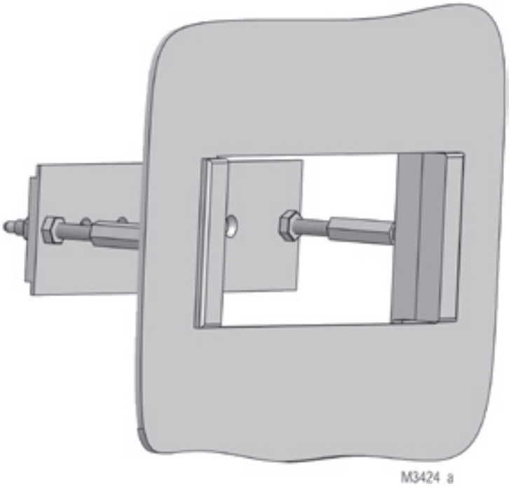
For universal use with:
- R-series devices of 17.5 to 105mm width
- Easy mounting
Connection Examples

1) Auxiliary voltage UH (A1(+)/A2) can also be sourced from the monitored voltage system.
The voltage range of the auxiliary supply has to be taken into account.
2) Control input X1/X2 for external combined Test-/Reset-button:
| Control approx. 1 s: | Test function |
|---|---|
| Control > 3 s: | Reset function |
Characteristics
E. Dold & Söhne GmbH & Co. KG
D-78120 Furtwangen
Bregstraße 18
Phone +49 7723 654-0
Fax +49 7723 654356
dold-relays@dold.com
www.dold.com
07.07.23 en / 755A
Read User Manual Online (PDF format)
Read User Manual Online (PDF format) >>