hanatek AFT Advanced Friction Tester User Manual
- October 30, 2023
- hanatek
Table of Contents
hanatek AFT Advanced Friction Tester User Manual

Who measures slip/friction?
Friction testing is extensively used in the packaging industry to measure the
“sloppiness” of a product, with the aim of predicting feeding and running
speed on an automatic gluing, erecting, filling or packaging line.
Other industries that test for slip include the paper industry (for the automatic feeding of photocopy paper, envelopes and banknotes), flooring manufacturers (for the anti slip properties of polishes), plastic manufacturers (the frictional properties of packaging).
What is slip/ friction?
A product’s “slippiness” is characterised by its coefficients of friction
Static coefficient of friction = Fs/N
Dynamic coefficient of friction = Fd/N
Where Fs is the maximum static frictional force and the Fd is the average dynamic frictional force. N is the Normal force, i.e. the force of gravity acting on the sample and test sled.
In practical terms, the static slip relates to the force required to get two resting surfaces moving, dynamic slip is the smaller force that is required to keep the surfaces moving once this initial “inertia” is overcome.
These values are expressed as ratios and do not have units, they are quoted as a decimal value between 0 and 1, for example a surface might have static slip coefficient of 0.35 and a dynamic slip coefficient of 0.18.
How is Coefficient of Friction Measured (COF)?
All methods of COF measurement involve preparing a sample into two flat
pieces, the samples are placed together and a weight is applied (the normal)
force. One of the samples is held in a fixed position, a force is applied to
the other sample until they begin to slip against one another
Flat Bed Friction Testing
To measure Static and Dynamic coefficients of friction it is necessary to use
a fixed bed instrument. These instruments use a motor to pull a sled across
the sample, using a load cell to measure the forces. Original slip testing
instruments were converted tensile testers that used a cord to pull the
sample. The use of a cord has now been removed from most friction measurement
standards due to the uncertainty added by its own elasticity and problems with
sample positioning.
The Advanced Friction Tester from Hanatek uses mechanical linkages to apply the force and uses automatic sled placement for very accurate sample positioning with variable dwell time before testing.
How can Coefficient of Friction (COF) Values relate to packaging speeds?
COF can often be related to the feeding and running attributes of products,
for example food cartons have a slip coefficient that is related to the type
of varnish applied, how well it has been cured and how thickly it has been
applied.
Cartons that have a very low static coefficient of friction may have handling difficulties as they will tend to slide apart and are difficult to place into feeding hoppers.
In contrast products which have a high coefficient of friction will tend to stick together and can prone to misfeeding due to multiple cartons entering the packaging line.
Different packaging lines will often require products with specific surface frictional profiles to achieve their highest running and feeding speeds, it is only by measuring and specifying these values that a manufacturer can achieve maximum productivity
What parameters affect Coefficient of Friction (COF) Values?
COF is primarily influenced by the chemical composition of the surface and its
physical profile. In packaging the surface chemistry is often related to
coatings applied to a carton or the additives in a plastics film. In the paper
and board making industries the friction characteristics are related to the
physical profile of the sample- paper fibres, coating composition and
smoothness etc.
How can detailed Frictional Force measurement help improve Productivity?
In addition to simple static and dynamic COF values the Hanatek Advanced
Friction Tester produces detailed force curves which detail the surface
characteristics across the test area.These force curves identify any
inconsistencies on the sample surface that may reduce packing or feeding
performance in the production environment by
The unique strength of the Hanatek Advanced Friction Tester is that profiles can be overlayed for comparison, allowing identification of substrate or coating changes that can cause problems with product runnability.
This powerful feature can highlight subtle differences in substrates or coatings that allow the user to fine tune their product for their production conditions giving optimum feeding, running and packing speeds
PACKING LIST
- AFT Friction Tester
- 2 x magnetic sample mounting bars
- 2 x USB data cables
- Touch screen computer
- Mouse and keyboard
- Computer power supply
- Hanatek USB data pen
- 1x AFT mains cable
- Friction template
- 200g film sled
- Calibration check pulley attachment
- 100g calibration check test weight
- Foot adjustment spanner
- Pulley attachment screwdriver
- Craft knife
- Bulls-eye spirit level
OPTIONAL EXTRAS
-
Tear test kit
-
Peel test kit
-
Block test kit
-
ISO 15359 paper and board test kit
WARNING – THE HANATEK AFT HAS MOVING PARTS WHICH MAY CONSTITUTE A PINCHING
RISK FOR FINGERS.
REASONABLE CARE MUST BE TAKEN AT ALL TIMES – DO NOT TOUCH THE MOVING PARTS DURING OPERATION AND ENSURE HAIR AND CLOTHING IS KEPT CLEAR.
ASSEMBLY
-
Unpack the unit carefully and check the contents against the packing list.
-
Place the instrument on a suitable bench. Avoid using the instrument in areas where vibration may affect the readings; i.e. close to heavy machinery.
-
Ensure the instrument is level before use. Place a spirit level central on the measurement platen and adjust the feet until the spirit level bubble remains central. This is important and must be periodically checked and adjusted every time the equipment is moved.
-
Plug the instrument and touch screen into a suitable main supply using the supplied mains leads.
-
Plug the two data cables (USB type B) into the back of the friction tester instrument.
Data and motor control cables in the back of the AFT

-
Plug the other end of the cables into any two free USB ports on the touch screen unit (the bottom RHS ports are suggested).
For normal operation and testing there is no need to plug in supplied mouse and keyboard.
USB cables on bottom RHS of touch screen.

POWER UP
BEWARE – THE HANATEK AFT IS FITTED WITH A 20N LOAD CELL. ANY FORCE ABOVE
2KG APPLIED TO THE LOAD CELL MAY RESULT IN CATASTROPHIC DAMAGE. CARE MUST BE
TAKEN TO AVOID CRASHING THE LOAD CELL INTO OBSTRUCTIONS LEFT ON THE PLATEN
DURING MEASUREMENT OR RETURN TO HOME POSITION.
HIGHER FORCE LOAD CELLS ARE AVAILABLE UPON REQUESTCONTACT HANATEK FOR MORE DETAILS
- Press the power up button on the touch screen.
The instrument and touch screen will power up.

SET UP/ADD PRINTER
Follow the set up instructions supplied with the instrument for a windows vista PC. It may be necessary to plug in the keyboard and mouse to successfully complete this installation.
The Hanatek AFT software will automatically print to the default printer. See windows help for more details.
START SOFTWARE
- Double tap on the friction tester ICON on the main screen and the software will start, the instrument is now ready for use.
PASSWORD PROTECTION
If you want to run password protection on the instrument (this stops the operator altering and deleting test methods and results), a password should be set up now.
- Go to MAIN MENU >OPTIONS>PASSWORD PROTECTION Press the help button for graphical instructions.
- The instrument will prompt for a password- the factory default password is “Rhopoint” (note: capital R).
- Type this password in using the on-screen keyboard. The instrument will now allow the user to change and activate password protection.
Before running a test it is advisable to become familiar with the test methods and equipment used.
CALIBRATION CHECK
If required it is possible to check the instrument calibration. A period calibration check is recommended (every 1-2 months).
- Go to MAIN MENU >OPTIONS>CALIBRATION CHECK Press the help button for full graphical instruction.
CALIBRATION
The instrument has a four-point calibration that is used to linearise the loadcell.
The loadcell should be calibrated on an annual basis.
Go to MAIN MENU >OPTIONS>CALIBRATION
WARNING- CALIBRATION SHOULD ONLY BE ATTEMPTED BY AUTHORISED CALIBRATION PERSONNEL. FAILURE TO ADHERE TO A PRESET CALIBRATION ROUTINE WILL RESULT IN ERRONEOUS READINGS AND POSSIBLE DAMAGE TO THE INSTRUMENT. CONTACT HANATEK FOR MORE DETAILS.
VIEW TEST INSTRUCTIONS
- Go to MAIN MENU >OPTIONS>TEST INSTRUCTIONS Press the help button for graphical instructions.
All tests methods have full graphical instructions.
Optional tests require additional equipment- peel testing; tear testing, block testing and ISO 15359 Paper and Board Testing. For further information and purchase information contact Hanatek.
CREATING AND EDITING TEST METHODS
Hanatek friction tester ISO/ASTM/TAPPI/FINAT test methods contain
information about test set up only- dwell times, speed, distance etc. For full
details on running tests within the listed standard it is always advisable to
purchase a copy of the standard. The full standards contain details about
sample preparation, conditioning and testing that it is not possible to list
within the AFT software.
Testing standards are updated and reviewed constantly; it is the user’s responsibility to ensure test methods are up to date, accurate and relevant to their industry.
- Go to MAIN MENU >CREATE/MODIFY TEST METHOD Press the help button for graphical instructions.
- Select the relevant test method and create/modify as required.
RUNNING A TEST
-
Go to MAIN MENU>PERFORM TEST
Press the help button for graphical instructions.
EXPORTING/PRINTING RESULTS -
Go to MAIN MENU >VIEW PREVIOUS TEST RESULTS Press the help button for graphical instructions.
Press the DETAILS button.
To EXPORT results plug a suitable USB data pen into any free USB port. Press the EXPORT button. The results will be as a .txt file that can be imported into any commercial spreadsheet software.
To PRINT results ensure a windows printer is attached and correctly setup. Press the PRINT button.
OPTIONAL EXTRAS
Peel test attachment
Peel 180
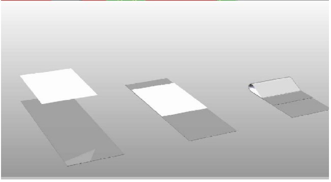
To run the tests select the following parts.

Place the samples to be tested face to face, or on a backing sheet. Two strips
of paper at the end to stop them from sticking.

Use the template to cut out the correct test size

Make up some test loops using tape and some paper. These will stick on the end
of the sample and allow the hook to mount onto the sample.

Stick the sample onto the sample holder using double sided tape.

Mount the test equipment onto the AFT as shown.

The peel sample holder mount is secured onto the end of the AFT with two M3 screws. The sample holder will slot into place.
The peel hook is mounted to the load cell using the sled link.
The sample is now ready for testing.
To run the tests select the following parts.
The sample should be cut into strips so they fit on the peel test wheel. The template can be to cut out the correct test size
Make up some test loops using tape and some paper. These will stick on the end
of the sample and allow the hook to mount onto the sample.
Mount the tape onto the peel test wheel and mount the test equipment onto the
AFT as shown.

The peel test wheel is secured onto the end of the AFT with two M3 screws. The
wheel can be removed from the holder for easier access if required. The peel
hook is mounted to the load cell using the sled link.

HEATED BED ATTACHMENT
The heated bed attachment is an optional extra that allows the friction of films and other materials to be measured at elevated temperatures.
ASSEMBLY
-
Unpack the heated bed attachment.

-
Power up the friction tester and enter the options menu. Click on Home position.
-
Use the raise and lower buttons to ensure the lift mechanism is in the down position.
-
Adjust the height of the load cell by unscrewing the knob, lift the load cell to its highest position.
-
Carefully place the heated bed on the friction tester measurement platen, sliding it carefully under the load cell.
-
Line up the holes in the measurement platen with the four lifting posts. Press the raise button to allow access to the lifting posts.

-
Screw in the four lifting post extensions.
-
Press the raise/lower buttons on the home position page to ensure the lift mechanism functions correctly.
-
Screw in the two silver fixing knobs to fix the heated bed to the friction tester.
-
Plug the temperature control unit into a suitable earthed power socket. For additional safety it is recommended that a RCD circuit breaker is also used.

OPERATION
- Use the up/down buttons to select the test temperature on the heater controller (120 Degrees C maximum).
- The unit will immediately begin heating
- The actual temperature is displayed on the top line of the controller, the target is displayed underneath.
- Allow the bed to reach temperature and stabilise, the heated bed is then ready for use.

WARNING- THE HEATED BED REACHES TEMPERATURES THAT CAN CAUSE BURNS. WEAR
SUITABLE PROTECTIVE CLOTHING/GLOVES AT ALL TIMES DURING TESTING.
ENSURE THAT THE PLASTIC GUARD IS LEFT IN THE DOWN POSITION IF THE HEATED BED IS AT ELEVATED TEMPERATURES.
SERVICE
Contact- HANATEK Instruments:
Telephone No: +44 (0)1424 739623
Fax Number: +44 (0)1424 730600
E-mail:
sales@hanatekinstruments.com
Web Site: www.hanatekinstruments.com
EU Directive 2002/96/EC on WEEE (Waste Electrical & Electronic Equipment) and RoHS (Restriction of the use of certain Hazardous Substances).
The European Union’s Directive on Restriction of the use of certain Hazardous Substances in electrical and electronic equipment (ROHS) defines each of 10 categories of electrical and electronic equipment in Annex I . Category 9 is defined as follows:
Monitoring and control instruments Smoke detector Heating regulators Thermostats Measuring, weighing, or adjusting appliances for household or as laboratory equipment Other monitoring and control instruments used in industrial installations (e.g. in control panels)
The RoHS Directive defines the scope of restrictions in Article 2 as follows:
“1. Without prejudice to Article 6, this Directive shall apply to electrical and electronic equipment falling under the categories I, 2, 3, 4, 5, 6, 7 and 10 set out in Annex IA to Directive No 2002/96/EC (WEEE) and to electric light bulbs, and luminaires in households.”
This product is supplied as a Monitoring and Control instrument and as such falls within category 9 of the EU directive 2002/96/EC and so is excluded from restrictions under the scope of the RoHS Directive.
The Waste Electrical and Electronic Equipment Directive is intended to reduce the amount of harmful substances that are added to the environment by the inappropriate disposal of these products through municipal waste.
Some of the materials contained in electrical and electronic products can damage the environment and are potentially hazardous to human health; for this reason the products are marked with the crossed out wheelie bin symbol which indicates that they must not be disposed of via unsorted municipal waste.
Rhopoint Instruments Ltd have arranged a means for our customers to have products that have reached the end of their useful life safely recycled. We encourage all end users to us at the end of the product’s life to return their purchase to as for recycling as per Article 9 of the WEEE Directive.
Please contact us on +44 (0) 1424-739622 and we will advise on the process for returning these waste products so we can all contribute to the safe recycling of these materials.
EC DECLERATION OF CONFORMITY
Rhopoint Instruments Ltd, Beeching Road, Bexhill on Sea, East Sussex, TN39 3LG
DECLARE UNDER OUR SOLE RESPONSIBILITY THAT THE PRODUCTS
Rhopoint Instruments Ltd 09 November 2011
Tony Burrows, Managing Director

References
- Rhopoint Instruments | Appearance & Measurement Experts
- Rhopoint Instruments | Appearance & Measurement Experts
Read User Manual Online (PDF format)
Read User Manual Online (PDF format) >>