SVAB Quantum Tool Recognition User Manual
- June 6, 2024
- SVAB
Table of Contents
![]()
Quantum Tool Recognitio n
User manual

Introduction
General
Quantum Tool Recognition is a system for wireless tool recognition on
excavators. This is the only usage intended for this product. All other usages
of this machine, without written permission from SVAB, are strictly
prohibited.
This document gives instructions on how to do installation work on a Quantum
Tool Recognition system. SVAB reserves the right to change the contents of
this instruction at any time without further notice.
SVAB develops and produces its products in accordance with European
legislation and the machinery directive 2006/42/EG. The CE marking shows that
the system fulfills the directive of electromagnetic compatibility EMC, RoHS,
and radio directive RED.
This installation instruction shall be used in the technical file which will
be the base for
the final CE marking of the machine. Therefore, the checklist in this
instruction shall be thoroughly performed, completely filled out, and signed
by the responsible fitter. Save this instruction in the technical file.
The installation of the system referred to in this document is to be performed
by experienced personnel. If there are unclarities regarding the use,
installation, understanding of the system, or regarding this document –
disengage the installation work and contact the system provider for
information. By using common sense you can avoid accidents from happening
yourself
This instruction is protected by copyright and may not be reproduced,
distributed, or altered. Violation of the law may lead to prosecutions and
fines, imprisonment, or a duty to pay compensation to the creator/proprietor.
FCC and ISED
Changes or modifications to the equipment not expressly approved by the party
responsible for compliance could void the user’s authority to operate the
equipment.
This device complies with Part 15 of the FCC Rules. Operation is subject to
the following two conditions:
(1) this device may not cause harmful interference, and (2) this device must
accept any interference received, including interference that may cause
undesired operation.
To comply with FCC/IC RF exposure limits for general population/uncontrolled
exposure, the antenna(s) used for this transmitter must be installed to
provide a separation distance of at least 20 cm from any persons and must not
be co-located or operating in conjunction with any other antenna or
transmitter.
NOTE: This equipment has been tested and found to comply with the limits
for a Class B digital device, pursuant to Part 15 of the FCC Rules. These
limits are designed to provide reasonable protection against harmful
interference in a residential installation. This equipment generates, uses,
and can radiate radio frequency energy and, if not installed and used in
accordance with the instructions, may cause harmful interference to radio
communications. However, there is no guarantee that interference will not
occur in a particular installation.
If this equipment does cause harmful interference to radio or television
reception, which can be determined by turning the equipment off and on, the
user is encouraged to try to correct the interference by one or more of the
following measures:
- Reorient or relocate the receiving antenna.
- Increase the separation between the equipment and receiver.
- Connect the equipment into an outlet on a circuit different from that to which the receiver is connected.
- Consult the dealer or an experienced radio/TV technician for help.
RSS standard
This equipment is exempt from the routine RF exposure evaluation requirement
of RSS-102. This equipment should be installed and operated with a minimum
distance of 20 cm between the antenna and the user or bystanders. This device
contains license-exempt transmitter(s)/receiver(s) that comply with
Innovation, Science, and Economic Development Canada’s license-exempt RSS(s).
Operation is subject to the following two conditions:
- This device may not cause interference.
- This device must accept any interference, including interference that may cause undesired operation of the device.
CAN ICES-3 (B)/NMB-3(B)
Support
Contact SVAB at: SVAB, Ulvsättersgatan 2SE-694 35 Hallsberg
Phone: +46 (0)582 152 30 (main) +46 (0)0582 152 33 (Support)
On our website www.svab.se you will find additional
information.
Approved areas of use
If you are unsure whether the function is allowed to control, always ask a
technician from your system provider.
Approved areas of use for Quantum ToolRec:
- Tool recognition on excavator
- Provide input signal to compatible systems
Quantum shall only be used for approved areas of use and functions as
mentioned above.
SVAB will not take part in injuries or accidents that occur due to
unauthorized use.
Environment
As part of our environmental commitment, we strive for our products to have an as little environmental impact as possible throughout the lifecycle. This means there are things to consider during the installation.
- All assembly/disassembly must be done according to national requirements and local regulations.
- Recycle waste according to national requirements and local regulations.
Technical Description
System overview
| Pos | Artikel | Benämning |
|---|---|---|
| 1 | P-0000963 | Quantum hub |
| 2 | P-0000966 | TRM |
| 3 | P-0001345 | Cable supply Quantum Hub |
| 4 | P-0001346 | Cable Quick coupler signal Quantum Hub |
| 5 | P-0000585 | Connecting cable Digging system |
| 6 | P-0000723 | M12 Connector male, straight 5 – pole |
| 7 | n/a | Quantum App (Google Play/App store) |
| 8a | 200586 | Jumper cable M8, 0,3 m |
| 8b | 149209 | Jumper cable M8, 1 m |
| 8c | 149207 | Jumper cable M8, 2 m |
| 9 | P-0001304 | Cover TRM |
Main parts
Quantum hub
The hub consists of the following main parts:
- CAN1 / 8-36 VDC
- I/O
- CAN2
- Diodes
- Nameplate
TRM (tool Recognition Module)
The TRM consists of the following main parts:
- Screw
- Cover
- Seal
- Battery
- Lower part
Technical data TRM
Dimensions
System
| | Unit| Remark
---|---|---|---
Min| Nom| Max
Mass| | 90| | g|
Material| | PC/PBT| | |
Operating temp| – 40| | + 70| C|
Storage temp| – 40| | + 85| C|
Voltage feed| 1.8| 3.6| 3.9| V|
Battery time| | | 5| år| Up to 5 years, depending on the degree of use
and environment
IP-rating| | IP67| | |
Bluetooth
| Description | Kommentar |
|---|---|
| Bluetooth | Bluetooth 4.1 |
| Frequency | From 2.4 GHz to 2.4835 GHz (ISM band) |
| Range | up tol 30 m |
Technical data HUB

System
| | Enhet| Kommentar
---|---|---|---
Min| Nom| Max
Vikt| | 180| | g|
Material| | PA6| | |
Driftstemp| – 20| | + 70| C|
Förvaringstemp| – 20| | + 85| C|
Spänningsmatn| 7.5| 12/24| 36| V|
CAN motstånd| | | | | Software selectable 120 Ω, 600 Ω, not terminated
IP-klassning| | IP50| | |
Bluetooth
| Description | Kommentar |
|---|---|
| Bluetooth | Bluetooth 4.1 |
| Frequency | From 2.4 GHz to 2.4835 GHz (ISM band) |
| Range | up tol 30 m |
Funktion
Tool recognition
Quantum Tool Recognition is a system for wireless tool recognition on
excavators. The system identifies which tool is connected to the excavator’s
attachment or to the tiltrotator’s attachment. Tool Recognition is based on
each tool being equipped with a compact and robust battery-powered device
(TRM) that communicates wirelessly with a controller in the cabin(Quantum
HUB).
The tiltrotator and/or machine quick coupler is connected to the system to
detect when a change of tools occurs. In cases where the machine is equipped
with a Quantum or MACS RT-based tiltrotator control system, the information is
shared when a tool change under the tiltrotator through the CAN bus. When
initiating a change, the system starts scanning for moving tools. The system
uses several smart conditions to identify the correct tools.
CAN-bus – interface towards external systems
The system hub can transmit the information to other control systems in the
excavator via the CAN bus. This way, these systems can adapt to each tool. An
example of a function is to automatically indicate the correct tool for the
machine’s GPS / 3D excavation system without the operator having to manually
enter it, or to automatically change settings in a Tiltrotator control system
based on the tool type.
Tracking of tools and machine
The system stores the user’s smartphone GPS position in the cloud and connects
it to the tool and machine shown on a map in the app, provided that the user
has:
- Downloaded the Quantum app to his/her smartphone
- Approved that the app has access to location information
- Bluetooth connection with HUB and/or TRM devices
- Internet Access
The information about the position of a tool or machine is also shared by
other users who have a Bluetooth connection with any Quantum HUB or TRM
device. It is enough for someone who has the Quantum app installed on their
smartphone to pass a HUB or TRM and get connected via Bluetooth to update the
location in the cloud. The information is sent anonymously and is displayed
only for those users who registered the current machine or device in their
app.
Operating time and service intervals
Quantum Tool Recognition together with the Quantum app also keeps track of the
machine and tool’s operating time. The machine’s operating time is measured in
time as the hub has been powered, the tool’s operating time is measured in
time as the TRM unit has been connected to the HUB and at the same time is in
motion.
In the app, you can define multiple service intervals for both the machine and
the tool, the app will then notify you via notifications to it when it’s time
for service.
Start using Quantum ToolRec
1. Quantum starts when the electronics of the machine are activated by the ignition.
Start the Quantum hub
Power up the machine
The Quantum hub will start and the diodes will start to flash. The LEDs are
called (from the left): LED 1, LED 2, LED 3, and LED 4.
LED 1 (Heartbeat), LED 2(TOOLREC-searching),
LED 3 (quick coupler), LED 4 (TOOLREC-status)
2. Check that LED 1 is flashing green. As long as the hub is running, the led will flash.
3. LED 2 flashes blue when searching for a tool. If LED 2 flashes green, it searches for a tilt rotator. If LED 2 flashes blue and green respectively, it searches for both tilt rotator and tools.
4. Check the lower coupler function by activating it. LED 3 lights up with a green steady light.
5. Check the upper coupler function by activating it. LED 3 lights up with a
red steady light. If both couplers are open, LED 4 lights up with a yellow
light.
6. When a tiltrotator has been identified, LED 4 lights up with a green
steady light. When a tool has been identified, LED 4 lights up with a blue
steady light
7. LED 4 lights up with a steady white light when both the tilt rotator and a tool have been identified.
Quantum App
Registration of users, machines, and tools
Register a user
Download the SVAB Quantum app from App Store or Google Play.
-
Start by creating a new user.
-
Enter user information and password. Click ”Next”.
You need to accept the license agreement in order to get to the next step in the registration. -
Wait for a confirmation mail and follow the instructions in the mail.
-
Your registration will be confirmed
Add a pre-registered machine
-
Go to ”Machines” to register a new machine.
Please note that the machine must be running in order for the system to function -
Press the + sign to scan for and register machines.
If your machine was configured in a workshop, your machine will show up as a machine nearby. -
Click on the machine to open the profile.
-
To edit the given information, click on ”Edit”. From here, you can change the name and change or add a picture.
-
Press ”Save” when you are done. The machine is added to your list.
Register a new machine
If the machine hasn’t been registered before, it needs to register from start.
-
Go to ”Machines” to register a new machine
Please note that the machine must be running in order for the system to function -
Press the + – sign to scan for and register machines
-
The machine will show up as an unknown machine. Click on the machine to register. Name the machine and add a picture if desired.
-
Press ”Save” when you are done. The machine is added to your list.
Add a pre-registered tool
-
Go to ” Work tools” to register a tool.
Please note that the machine must be running in order for the system to function
If your machine was configured in a work shop, one or several tools will be available in the app. -
Press the + – sign to scan and register for a tool.
-
Click on the tool to be registered.
-
To edit given information, press ”Edit”. From here, you can change your name or add or change a picture if desired.
-
Press ”Save” when you are done. The tool will be added to your list.
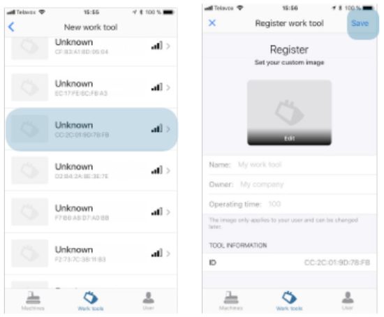
Register a new tool
If the tool hasn’t been registered before, it needs to register from the
start.
- Go to ” Work tools” to register a tool.
- Press the + – sign to scan and register for a tool.
- The tool will show up as ”Unknown”, with a MAC address. Compare the numbers on the installed TRM module.
- Select the tool to be registered. Name the tool and add a picture if desired.
- Press ”Save” when you are done. The tool will be added to your list.
Tiltrotator TRM
The tilt rotator TRM is predefined by the factory and will show up on the
screen
Connect machines and tools
Connect a machine
You can have several machines added to your list. When you start your machine,
Quantum hub will start up and scan for machines and tools.
You can see if your machine is available by looking at the strength of the
signal, to the right.
Connect a tool
- Start the machine.
- Activate the quick coupler and lock to a tool.
- Quantum Toolrec will now start to scan for and connect to the tool in the app.
- You can verify that the tool is connected to your machine under ”Working tools”.
Change tools
- Activate the quick coupler and release the tool.
- Lock on to the new tool.
- Quantum ToolRec will start a new scan and connects to the tool.
Under ”Map” the position of each machine and tool is shown.

Service
Under ”Service” or for your tool. These will end up under ”Notifications” when it’s time to perform a measurement. You can also see the operating time for your machine or tool.
- Press the +-sign to create an activity.
- Name the activity and the hours for the interval. Press ”Save”.

Maintenance
Maintenance schedule
| Description | Maintenance | Interval | Remark |
|---|---|---|---|
| TRM | REplace battery | 5 yrs | |
| Replace cover | When necessary | ||
| Replace TRM | When necessary |
Maintenance instructions
Preparations before maintenance
- Make sure that the machine is turned off and the excavator boom is lowered.
- Clean the area around the TRM to avoid dirt from entering the module when dismounting.
Replace battery
-
Remove two screws holding the cover.
-
Use a screwdriver to separate the cover from the lower part.
-
Remove the seal between the cover and the lower part.
-
Replace the battery in the unit.
Make sure to only use original batteries from SVAB. The unit will not work with ordinary 1.5 V batteries. -
Install a new seal [1] between the cover and the lower part. Make sure that the seal fits the groove properly.
-
Put the cover back.
Make sure to turn the cover in the correct position so the notch [2] fits the battery. -
Reinstall the 2 screws. Tightening torque 0.8 Nm.
The TRM module should be mounted on the tool at room temperature for results. The temperature may not go under – 10 gra C.
The module is delivered with the battery, sealing, and screws on the side.
-
Remove the old TRM from the tool
-
Clean the surface before mounting the new module.
-
Remove the cover on the module and install the battery.
Install the seal. Make sure that the seal fits the groove properly.
 -
Put the cover back.
Make sure to turn the cover in the correct position so the notch [2] fits the battery. -
Note the MAC address on the module. This number will show up in the app later on. You will find the label on the side of the module. Example of a MAC- address: C6:6D:D5:27:4F: B5.
Recommended spare parts
TRM

| Pos | Part | Description |
|---|---|---|
| 1 | P-0001366 | TRM |
| 2 | P-0000967 | Battery kit |
Recycling
Replaced parts are recycled according to local laws and regulations or are returned to SVAB.
![]()
Read User Manual Online (PDF format)
Read User Manual Online (PDF format) >>