WB-SIGE-400 Waste Bin Instruction Manual
- June 1, 2024
- SIGE
Table of Contents
WB-SIGE-400 Waste Bin

TOOLS

Maintenance
Clean with a soft, dry cloth. Avoid using solvents or abrasive.


FEATURES
- N°6 4,2×6,5 :Self tapping TC screw
- N°8 3,9×13 : Self-tapping TC screw
- N°4 M5x8 mm: Screws
- N°4 M5x13′ :Special hex key screw
- N°1 :Allen key

PARTS
- A. N°1 :Frame
- B. N°2 :Adjustable carter
- C. N°2: Door stabilizing elements
- D. N’2:Cover
- E.: Wastebin kit
INSTALLATION INSTRUCTION
-
Fix the drawer slides at the suggested height according to the capacity of the bins

-
Assemble the back of the drawer (not supplied) on the drawer system.

-
N°4 M5x13
Pre-mount the four M5x13 (special screws) on the carters B, as shown.
-
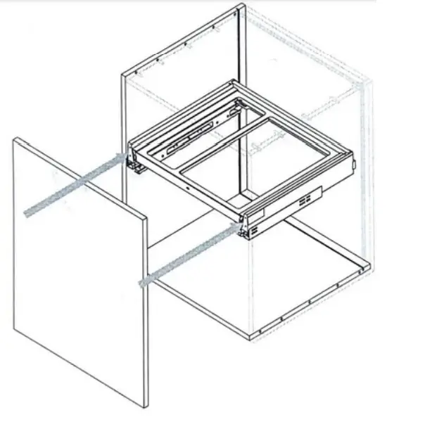
Assemble the frame A with the carters B, as shown, to obtain the chassis.

-
Turn upside down and assemble the chassis with the drawer sides, as shown.
-
Attention: mount the chassis in the correct way, as shown in the boxes, according to the type of drawer wend

-
N°6 4,2×6,5
Fix the chassis into the drawer using the six 4.2×6.5 screws then turn it upside down.
-
Mount the drawer on the slides.

-
Mount the door on the drawer.
-
Adjust the door through the drawer adjustment system.

-
Fix the frame A to the carters B by tightening the four M5x13 special screws from below with the allen key.

-
N°4 M5x8
Pre-mount four M5x8 screws on the front side of the carters B. Hang the door stabilizing elements C on the pre-mounted screws. -
N°6 3,9×13
Position the door stabilizing elements C in contact with the door then tighten the four M5x8 screws, finally fix the stabilizing elements C to the door with six 3,9×13 screws
-
Mount the cover D.
-
Nº2 3,9×13
If you have a solid door, fix the frame A to the door with a 3,9×13 screw to increase the stability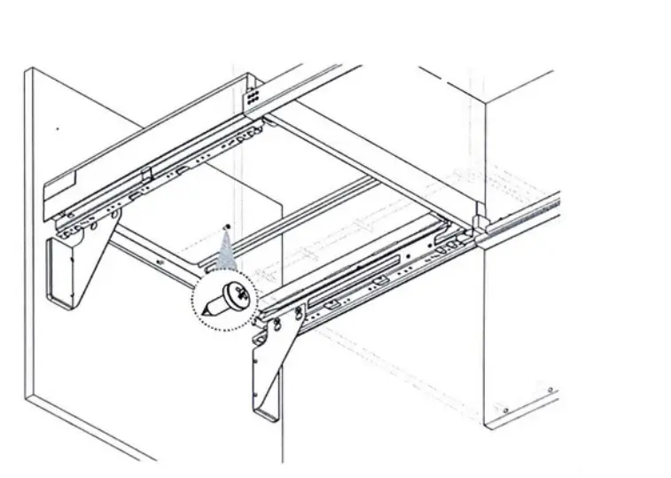
-
Place the bins.


Read User Manual Online (PDF format)
Read User Manual Online (PDF format) >>