SECPRO SL18XX Sliding Gate Opener Control Board Instruction Manual
- June 17, 2024
- SECPRO
Table of Contents
 Sliding Gate Opener
Packing List (standard)
| No. | Picture | Name | Quantity |
|---|---|---|---|
| 1 | Main engine | 1 | |
| 2 | Manual release key | 2 | |
| 3 | According to the model already choose | Remote control | 2 |
| 4 | Spring limit switch accessories box / Magnetic limit switch accessories | ||
| box | 1 | ||
| 4-1 | 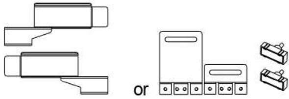| Spring limit switch block / Magnetic
limit switch block| 1
4-2| | Foundation bolt M10| 4
4-3| | Spring limit switch block
mounting screw M6X10
/ Magnetic limit switch block
mounting screw M6X18| 4
4-4| | Nut M10| 8
4-5| | Flat washer 010| 8
4-6| | Spring washer 010| 4
Packing list (Optional)
| No. | Picture | Name | Quantity |
|---|---|---|---|
| 1 | Metal rack | 1 m/pc | |
| 2 | Nylon rack | 1 m/pc | |
| 3 | Keypad ( different models are optional ) | 1 pc | |
| 4 | Flash lamp ( different models are optional ) | 1pc | |
| 5 | Photocell ( different models are optional ) | 1pair | |
| 6 | Mounting plate | 1piece |
Technical parameters
| Model | SLG54001 | SLG54002 | SLG54003 | SLG54004 |
|---|---|---|---|---|
| Power supply | 110VAC/50Hz | 110VAC/50Hz | 220VAC/50Hz | 220VAC/50Hz |
| Motor power | 400W | 400W | 400W | 400W |
| Gate moving speed | 11-13m/min | 11-13m/min | 11-13m/min | 11-13m/min |
| Maximum weight of gate | 1000Kg | 1000Kg | 1000Kg | 1000Kg |
| Remote control distance | ≥ 50m | ≥ 50m | ≥ 50m | ≥50m |
| Remote controlmode | Single button mode /Three button mode | Single button mode | ||
| /Three button mode | Single button mode /Three button mode | Single button mode |
/ Three button mode
Limit switch| Magnetic limit switch| Spring limit switch| Magnetic limit
switch| Spring limit switch
Noise| 60dB| 5.60dB| 5.60dB| 60dB
Output torque| 22N.m| 22N.m| 22N.m| 22N.m
Output shaft
height| 50mm| 50mm| 50mm| 50mm
Frequency| 433.92 MHz| 433.92 MHz| 433.92 MHz| 433.92 MHz
Working
temperature| -20°C – +70°C| -20°C – +70°C| -20°C – +70°C| -20°C – +70°C
Package weight| 16Kg| 16Kg| 16Kg| 16Kg
Model| SLG55505| SLG55506| SLG55507| SLG55508
Power supply| 110VAC/50Hz| 110VAC/50Hz| 220VAC/50Hz| 220VAC/50Hz
Motor power| 550W| 550W| 550W| 550W
Gate moving speed| 11-13m/min| 11-13m/min| 11-13m/min| 11-13m/min
Maximum weight of gate| 1500Kg| 1500Kg| 1500Kg| 1500Kg
Remote control distance| ≥ 50m| ≥ 50m| ≥ 50m| ≥ 50m
Remote control mode| Single button mode / Three button mode| Single button
mode / Three button mode| Single button mode / Three button
mode| Single button mode / Three button mode
Limit switch| Magnetic limit switch| Spring limit switch| Magnetic limit
switch| Spring limit switch
Noise| ≤ 60dB| ≤ 60dB| ≤ 60dB| ≤ 60dB
Output torque| 32N.m| 32N.m| 32N.m| 32N.m
Output shaft
height| 50mm| 50mm| 50mm| 50mm
Frequency| 433.92 MHz| 433.92 MHz| 433.92 MHz| 433.92 MHz
Working
temperature| -20°C – +70°C| -20°C – +70°C| -20°C – +70°C| -20°C – +70°C
Package weight| 17Kg| 17Kg| 17Kg| 17Kg
4.1 Installation drawing 
- Gate opener;
- Wireless keypad ;
- Gate;
- Infrared sensor;
- Alarm lamp;
- Safety stop block;
- Gear rack;
- Remote control;
4.2 Size of main engine and accessories
4.2.1 Size of main engine 
4.2.2 Size of mounting plate 
4.3 Installation procedures
4.3.1 Preparation work before installation
Please ensure that the sliding gate is correctly installed, the gate rail is
horizontal, and the gate can glide back and forth smoothly when moved by hands
before installing the gate opener.
Cable installation
Please bury the motor & power cable and controlling cable with PVC tube, and
use two PVC tubes to bury (motor & power cable) and (controlling cable)
separately, so as to guarantee normal operation of the gate opener and protect
the cables from damages.
Concrete pedestal
Please cast a concrete pedestal with the size of 500mm x 300mm and depth of
250mm in advance, so as to firmly install SLG5400X, SLG5550X gate opener.
Please verify whether the distance between the gate and gate opener is
suitable before casting the pedestal.
Embedded screws
4.3.2 Main engine installation
a) Dismantle the plastic housing on the main engine before installation and
keep relevant fasteners properly;
b) Please prepare the power line for connecting mounting plate and main engine
(the number of power supply cable core shall not be less than 3 PCS, the
sectional area of cable core shall not be lower than 1.5mm? and the length
shall be determined by users according to the field situation) due to
different installation environments;
c) Please unlock the main engine before installation, the unlock method is:
take out the key cover, insert the key, and open the manual release bar fill
it rotates by 90° as shown in Figure 5. Then turn the output gear and the gear
can be rotated easily; 
4.3.3 Gear rack installation
- Fix the mounting screws to the rack.
- Put the rack on the output gear, and weld the mounting screw to the gate (each screw with onesolder joints firstly).
- Unlock the motor and can pull the gate smoothly.
- Please check whether there is a fit clearance between rack and output gear, as shown in Figure 7.
- Weld all the mounting screws to the gate firmly.
- Make sure that all racks on the same straight line.
- Pull the gate after installed, make sure the entire trip is flexible no stuck.
 The fit clearance of output gear and rack is
shown in Figure 7 below:
The fit clearance of output gear and rack is
shown in Figure 7 below:
Warnings
-
To ensure safety, install safety stop blocks on both ends of the rails to prevent the gate out of the rail.
Before installing the main engine, make sure that the safety stop blocks are in place and whether it has the function of preventing the gate from moving out of the rail and out of the safety range. -
Please ensure that the main engine and its components have good mechanical properties, and the gate can operate flexibly when moved by hands before installing the main engine.
-
In this product, one control can drive one main engine only, otherwise, the control system will be damaged.
-
Earth leakage circuit breaker must be installed where the gate movement can be seen, and the minimum mounting height is 1.5m to protect it from being touched.
-
After installation, please check whether the mechanical property is good or not, whether gate movement after manual unlocking is flexible or not, and whether the infrared sensor (optional) is installed correctly and effectively.
4.3.4 Limit switch adjustment
Spring limit switch – The installation site of spring limit switch is
shown in Figure 8: The installation of spring limit switch stop
block is shown in Figure 9:
The installation of spring limit switch stop
block is shown in Figure 9: Magnetic limit switch – The
installation site of magnetic limit switch is shown in Figure 10:
Magnetic limit switch – The
installation site of magnetic limit switch is shown in Figure 10:  The installation of magnetic limit switch block is shown in
Figure 11:
The installation of magnetic limit switch block is shown in
Figure 11:
Note: The default setting is right side mounting. (According to actual
situation, please refer to the
“Note” of section 5.1 to adjust.)
Control board wiring
5.1 The opener should be install on the left side of the sliding door because
it is set as clockwise when delivery. If needs to install on the right side of
the sliding door, the DIP switch 3 should be changed into the opposite side.
5.2 Disconnect the power and connect the wires by professionals
5.3 Open the top cover of the motor, and connect the wires according to the
following figure (user just connects the interfaces of AC input, flash lamp,
external control switch, photocell and 24VAC output), then install the top
cover again after debugging.
SLIDING GATE OPENER CONTROL BOARD SL18XX USER MANUAL 2
I Safety Instruction
1.1 For security, please read instructions carefully before initial operation;
making sure that the power is off before connection.
1.2 Please clear the memory before initial operation. (Ref.: Erasing ALL
learned/memorized Transmitter
1.3 Do not learn the remote control when motor is operating in order to avoid
mis—operation.
1.3 The received signal may be interfered by other communication devices.
(e.g. the wireless control system with the same frequency range)
1.4 This product is only used for the equipment which will not cause life or
property hazards when a breakdown happens or its security risks have been
already eliminated
1.5 It should be applied in dry indoor place or in the electric appliance
place.
II Technical Index
2.1 Working voltage: 220VAC/110VAC,50Hz/60Hz
2.2 Temperature range: -20°C to 60°C
2.3 Loading capacity : 1 HP 220VAC; 0.5 HP 110VAC
2.4 Built-in fuse: electric circuit(0.5A); Motor(10A),Please exchange
appropriate FUSE accoding to LOADING capacity .
2.5 Soft-start time: Adjustable from 3s to 120s —-PT3 is to set up
2.7 fREQUENCY : 433.92MHz
2.8 Transmitter stored: 30PCS
2.9 Output voltage: AC24V
2.10 Output with electric lock: normally-closed contact
2.11 Output with flash lamp: AC220V/AC110V
2.12 External switch (open,stop,close in a loop)
2.13 External limit ( DIPS to select NO and NC)
2.14 External infrared (NC contact)
2.15 Auto close time is adjustable: (55,10s,30s are optional by using
DIP1,DIP2)
2.16 Soft start function is optional by DIP5
2.17 Installation at left or right side is optional by DIP6.
2.18 Single / three button control is optional by DIP7
2.19 Size: 1557738mm
2.20 Weight: 333g
III Wire connection 
IV Set up
4.1 Learning and erasing transmitters by receiver: Press the learning
button S3 in the board, LED DL2 is on, enters into the learning process; Press
the same button twice, LED blinks for several times, then off. The learning
process is successful. Press the learning button, continue pressing for 8s
until LED turns off; Release learning button, LED will be on (about 1s) and
then off; the erasing process is successful. (Ignore this step if transmitter
already matches the opener before delivery).The board can learn 30pcs
transmitters max.
Self-learning function: Use the transmitter that already has been learned
as old transmitter, press button 1 and button 2 at the same time and then
press button 2 to let it enters into the learning process .Press the same
button on the new transmitter twice.
The learning process done. In this way , new transmitter can be learned
without pressing the learning button on the control board.
4.3 External infrared switch: Photocell connector connects the NC contact
of photocell switch , DL4 LED turn on after the connection, And DL4 LED turn
off when blocking out the transmit or receive signal of photocell
artificially. Infrared sensor doesn’t react when door openning and the door
will reverse to limit point if photocell signal disconnect when door closing.
If no need of using photocell protection, make the connector of photocell
short circuit with terminated line(the connector is short circuit when leave
factory).
4.4 Quick running time set up: It is adjustable from 3s to 120s.
Adjust potentiometer PT3 (FastTime) to adjust the quick running time of motor.
It increases the time when adjust it Clockwise, reduces the time when
anti—Clockwise
4.5 Motor max running time = Quick running time + Soft stop time = 127
seconds Speed of quick running time is about 0.2 meter per second . Speed of
soft stop running time is about 0.06 meter per second.
4.6 Flash lamp: It keeps lighting when open or close the door .After door
is fully closed, it will keep lighting for 90 seconds.
4.7 DIP switch S5 logic function:
| DIP1 | DIP2 | Auto close time |
|---|---|---|
| OFF | OFF | No auto close |
| OFF | ON | 5S |
| ON | OFF | 10S |
| ON | ON | 30S |
| DIP6 | Right/left side installation | |
| --- | --- | |
| ON | ONor OFF can change the current operating | |
| OFF | direction of motor | |
| DIP3 | DIP4 | Function Cancel |
DIP7
ON| Single button control
OFF| Three button control
DIP5| Soft start function
ON| Turn on soft start function
OFF| Disable soft start funtion
DIP8
ON| External limit NC switch
OFF| External limit NO switch
V Operation Instruction
5.1 Three button control process (DIP 7 at OFF position) 5.2 Single button control process (DIP 7 at ON
position)
5.2 Single button control process (DIP 7 at ON
position) Description:
Single button control , press—open—press—stop— press—stop; Only the learned
button is effective in the transmitter, original button is not effective any
more when a new button has been learned in the same transmitter (For example,
button 1 was learned firstly, button 2 or 3 has been learned of the same
transmitter afterwards , then button 1 was not effective any more)
VI Notes
6.1. Photocell protection switch shall be examined regularly.
VII Model difference
Model| Working voltage| Transmitter stored (pcs)| Model| Working voltage|
SL1800| 220VAC| 30| SL1898| 220VAC|
SL1801| 220VAC| 300| SL1894| 220VAC|
SL1820| 110VAC| 30| SL1896| 110VAC|
SL1821| 110VAC| 300| SL1892| 110VAC|
The interpretation and ownership of this manual belong to Hiland company. Any
change of the product can be without prior notice.
Sliding gate opener SL
G5400XAC/SLG5550XAC (SLO7X0)
Read User Manual Online (PDF format)
Read User Manual Online (PDF format) >>