GigaDevice GD32350G-START Module User Guide
- June 4, 2024
- GigaDevice
Table of Contents
Semiconductor Inc GD32350G-START
User Guide
GD32350G-START Module
Summary
GD32350G-START board uses GD32F350G8 as the main controller. As a complete
development platform of GD32F3x0 powered by ARM® Cortex™-M4 core, the board
supports the full range of peripherals. It uses a mini-USB interface or AC/DC
adapter to supply 5V power. SWD, Reset, Boot, User button key, LED, and
Extension Pin are also included. This document details its hardware schematic
and the relevant applications.
Function Pin Assign
Table 2-1 Pin assignment
| Function | Pin | Description |
|---|---|---|
| LED | PA1 | LED1 |
| KEY | PAO | K1-User Key |
| RESET | K2-Reset | |
| USB | PA11 | USBDM |
| PAl2 | USBDP | |
| PA8 | USBCTR | |
| PA9 | USBVBUS |
Getting started
The START Board uses a mini-USB connecter or AC/DC adapter to get power, the hardware system power is +3.3V. A mini-USB cable is necessary to down programs. Select the correct boot mode and then power on, the LED3 will turn on, which indicates the power supply is ready. There are Keil versions and IAR versions of all projects. The Keil versions of the projects are created based on Keil MDK-ARM 4.74 uVision4. IAR versions of the projects is created based on IAR Embedded Workbench for ARM 7.40.2. During use, the following points should be noted:
- If you use Keil uVision4 to open the project, install the GD32F3x0_AddOn.2.0.0.exe to load the associated files.
- If you use Keil uVision5 to open the project, there are two ways to solve the “Device Missing (s)” problem. One is to install GigaDevice.GD32F3x0_DFP.2.0.0.pack. In the Project menu, select the Manage sub-menu, click on the “Version Migrate 5 Format…” menu, and the Keil uVision4 project will be converted to the Keil uVision5 project. Then add “C:\Keil_v5\ARM\Pack \ARM\CMSIS\4.2.0\CMSIS\Include” to C/C++ in Option for Target. The other is to install Addon directly. Select the installation directory of Keil uVision5 software, such as C:\Keil_v5, in the Destination Folder of Folder Selection. Select the corresponding device in Device of Option for Target and add C:\Keil_v5\ARM\Pack\ARM\CMSIS\4.2.0\CMSIS\Include” to C/C++ in Option for Target.
- If you use IAR to open the project, install IAR_GD32F3x0_ADDON.2.0.0.exe to load the associated files.
Hardware layout overview
Power supply
Figure 4-1 Schematic diagram of power supply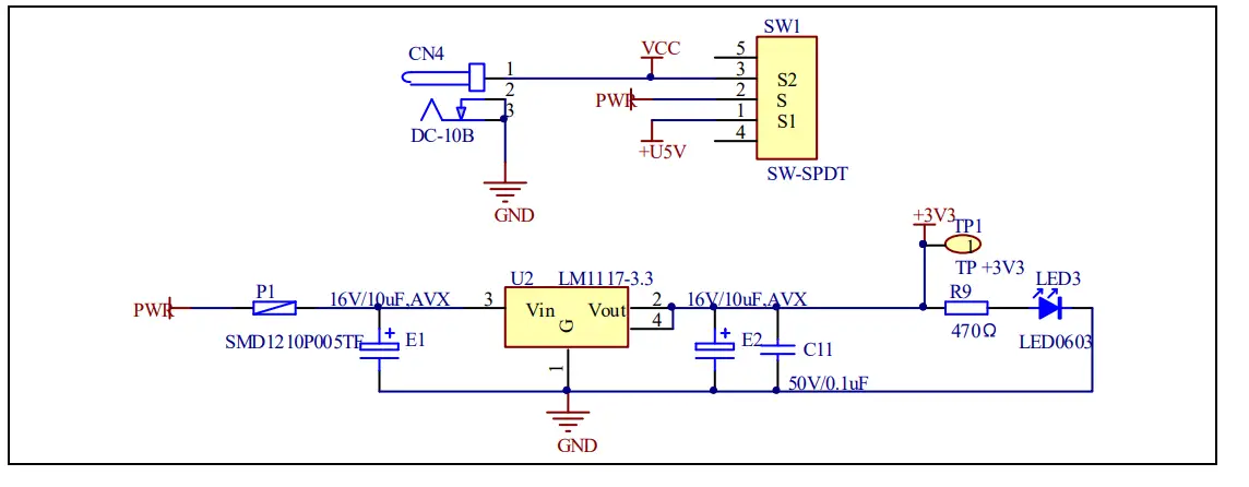
Boot option Figure 4-2 Schematic diagram of boot option
 Table 4-1
Boot configuration
Table 4-1
Boot configuration
| BOOT1 | BOOT0 | Boot Mode |
|---|---|---|
| Default | 2-3 | User memory |
| 1-2 | System memory | |
| Changed by ISP | 1-2 | SRAM memory |
LED
Figure 4-3 Schematic diagram of LED function

KEY
Figure 4-4 Schematic diagram of Key function
KEY
 USBFS
Figure 4-5 Schematic diagram of USBFS function
USBFS
Figure 4-5 Schematic diagram of USBFS function
 GD-Link
Figure 4-6 Schematic diagram of GD-Link function
 Extension
Figure 4-7 Schematic diagram of Extension Pin

MCU
Figure 4-8 Schematic diagram of MCU Pin

Routine use guide
GPIO_Running_Led
DEMO purpose
This Demo includes the following functions of GD32 MCU:
- Learn to use GPIO for controlling the LED
- Learn to use SysTick to generate a 1ms delay
GD32350G-START board has one LED. The LED1 is controlled by GPIO. This demo
will show how to light the LED.
DEMO running Result
Download the program <01_GPIO_Running_Led> to the board, the state of LED1 is
toggled every 1s.
GPIO_Key_Polling_mode
DEMO purpose
This Demo includes the following functions of GD32 MCU:
- Learn to use GPIO to control the LED and the KEY
- Learn to use SysTick to generate a 1ms delay
GD32350G-START board has two keys and one LED. The two keys are the Reset key
and the User key. The LED1 is controlled by GPIO.
This demo will show how to use the User key to control the LED1. When pressing
down the User Key, it will check the input value of the IO port. If the value
is 1, wait for 50ms. Then check the input value of the IO port again. If the
value is still 1, indicates that the button is pressed down successfully, and
lights the LED1.
DEMO running Result
Download the program <02_GPIO_Key_Polling_mode> to the board, first of all,
all the LEDs will be flashed once for the test. Then press down the User Key,
and LED1 will be turned on. Press down the User Key again, and LED1 will be
turned off.
EXTI_Key_Interrupt_mode
DEMO purpose
This Demo includes the following functions of GD32 MCU:
- Learn to use GPIO to control the LED and the KEY
- Learn to use EXTI to generate an external interrupt
GD32350G-START board has two keys and one LED. The two keys are the Reset key
and the User
key. The LED1 is controlled by GPIO.
This demo will show how to use EXTI interrupt line to control the LED1. When
pressing down the User Key, it will produce an interrupt. In the interrupt
service function, the demo will toggle LED1.
DEMO running Result
Download the program <03_EXTI_Key_Interrupt_mode> to the board, first of all,
all the LEDs will be flashed once for testing. Then press down the User Key,
and LED1 will be turned on.
Press down the User Key again, and LED1 will be turned off.
USB_FS
USBD_CDC_ACM
DEMO purpose
This demo includes the following functions of GD32 MCU:
- Learn how to use the USBFS peripheral
- Learn how to implement a USB CDC device
The Start board has one USBFS interface. In this demo, the Start board is
enumerated as a USB virtual COM port, which would be shown in the device
manager of the PC as below. This demo makes the USB device looks like a serial
port, and loops back the contents of a text file over the USB port. To run the
demo, input a message using the PC’s keyboard. Any data that shows in
HyperTerminal is received from the device.
 DEMO
running Result
DEMO
running Result
Download the program <04_USBFS\Device\CDC_ACM> to the Start board and run.
When you input a message through a computer keyboard, the HyperTerminal will
receive and show the message. For example, when you input “GigaDevice MCU”,
the HyperTerminal will get the message and show it as below.

USBH_MSC_Host
DEMO purpose
This demo includes the following functions of GD32 MCU:
- Learn to use the USBFS as an MSC host
- Learn the operation between the MSC host and the U-disk Start board integrates the USBFS module, and the module can be used as a USBFS device, a USBFS host, or an OTG device. This demo mainly shows how to use the USBFS as a USB MSC host to communicate with an external U-disk.
DEMO running Result
Insert the OTG cable to the USB port, download the program <04_USBFS\Host\MSC>
to the Start board, and run.
If an Udisk has been attached, firstly, press the user key, then this demo
will write the file to the Udisk. After a while, the file would have been
written in U-disk, the MSC host demo is the end and the LED1 will be on.
Revision history
Table 6-1 Revision history
| Revision No. | Description | Date |
|---|---|---|
| 1 | Initial Release | Jun.28, 2017 |
| 2 | Updated format across the whole document | Jun.1, 2019 |
Important Notice
This document is the property of GigaDevice Semiconductor Inc. and its
subsidiaries (the “Company”). This document, including any product of the
Company described in this document (the “Product”), is owned by the Company
under the intellectual property laws and treaties of the People’s Republic of
China and other jurisdictions worldwide. The Company reserves all rights under
such laws and treaties and does not grant any license under its patents,
copyrights, trademarks, or other intellectual property rights. The names and
brands of third parties referred thereto (if any) are the property of their
respective owner and referred to for identification purposes only. The Company
makes no warranty of any kind, express or implied, with regard to this
document or any Product, including, but not limited to, the implied warranties
of merchantability and fitness for a particular purpose. The Company does not
assume any liability arising out of the application or use of any Product
described in this document. Any information provided in this document is
provided only for reference purposes.
It is the responsibility of the user of this document to properly design,
program, and test the functionality and safety of any application made of this
information and any resulting product. Except for customized products that
have been expressly identified in the applicable agreement, the Products are
designed, developed, and/or manufactured for ordinary business, industrial,
personal, and/or household applications only. The Products are not designed,
intended, or authorized for use as components in systems designed or intended
for the operation of weapons, weapons systems, nuclear installations, atomic
energy control instruments, combustion control instruments, airplane or
spaceship instruments, transportation instruments, traffic signal instruments,
life-support devices or systems, other medical devices or systems (including
resuscitation
equipment and surgical implants), pollution control or hazardous substances
management, or other uses where the failure of the device or The product could
cause personal injury, death, property or environmental damage (“Unintended
Uses”). Customers shall take any and all actions to ensure using and sale of
the Products in accordance with the applicable laws and regulations. The
Company is not liable, in whole or in part, and customers shall and hereby do
release the Company as well as its suppliers and/or distributors from any
claim, damage, or other liability arising from or related to all Unintended
Uses of the Products. Customers shall indemnify and hold the Company as well
as its suppliers and/or distributors harmless from and against all claims,
costs, damages, and other liabilities, including claims for personal injury or
death, arising from or related to any Unintended Uses of the Products.
Information in this document is provided solely in connection with the
Products. The Company reserves the right to make changes, corrections,
modifications, or improvements to this document and the Products and services
described herein at any time, without notice.
© 2019 GigaDevice – All rights reserved
Read User Manual Online (PDF format)
Read User Manual Online (PDF format) >>