Power Rack HV4 Battery Energy Storage System Innovator User Manual
- June 15, 2024
- Power Rack
Table of Contents
- Statement of Law
- Safety Precautions
- Preface
- Introduction
- Product Specification
- Interface Definition
- Communication port
- Battery Management System(BMS)
- Voltage Protection
- Current Protection
- Temperature Protection
- Installation and Configuration
- Preparation for installation
- Environmental requirements
- Tools and data
- Technical preparation
- Unpacking inspection
- Engineering coordination
- Equipment installation
- Installation preparation
- Mechanical installation
- Installation method:
- Electrical installation
- Connecting inverter
- Maintenance
- Trouble shooting
- Replacement of main component
- Battery Maintenance
- Voltage Inspection:
- Storage Recommendations
- Shipment
- Read User Manual Online (PDF format)
- Download This Manual (PDF format)
Power Rack HV4 Battery Energy Storage System Innovator User Manual
Statement of Law
Copyright of this document belongs to Daqin New Energy Tech (Taizhou) Co., Ltd.
No part of this documentation maybe excerpted, reproduced, translated, annotated or duplicated in any form or by any means without the prior written authorization of Daqin New Energy Tech (Taizhou) Co., Ltd. All Rights Reserved.
This product complies with the design requirements of environmental protection and personal safety. The storage, use and disposal of the products shall be carried out in accordance with the product manual, relevant contract or relevant laws and regulations.
Customer can check the related information on the website of Daqin New Energy Tech(Taizhou) Co., Ltd when the product or technology is updated. Web URL:http://www.dyness-tech.com.cn
Please note that the product can be modified without prior notification.
Manual Version: V1.0
Revision History
| Revision NO. | Revision Date | Revision Reason |
|---|---|---|
| 1.0 | 2021.09.06 | First Published |
Safety Precautions
Warning
- Please do not put the battery into water or fire, in case of explosion or any other situation that might endanger your life.
- Please connect wires properly while installation, do not reverse connect.
- To avoid short circuit, please do not connect positive and negative poles with conductor on the same device.
- Please avoid any form of damage to battery, especially stab, hit, trample or strike.
- Please shut off the power completely when removing the device or reconnecting wires during the daily use or it could cause the danger of electric shock.
- Please use dry powder extinguisher to put out the flame when encountering a fir hazard, liquid extinguisher could result in the risk of explosion.
- For your safety, please do not arbitrarily dismantle any component in any circumstances. The maintenance must be implemented by authorized technical personnel or our company’s technical support. Device breakdown due to unauthorized operation will not be covered under warranty.
Caution
- The products have been strictly checked before shipment. Please contact us if you find any abnormal phenomena such as device outer case bulging.
- In order to ensure safety and normal use of the product, the equipment should be grounded properly before use.
- To assure the product normal operation, please make sure parameters among the relevant device are compatible and matched.
- Please do not mixed-use batteries from different manufacturers, different types antimodels, as well as old and new together.
- Ambient and storage method could impact the product life span, please comply with the operation environment instruction to ensure device works in proper condition.
- For long-term storage, the battery should be recharged once every 3 months, and the amount of electric charge shall exceed 80% of the rated capacity.
- Please charge the battery in 18 hours after it fully discharged or over-discharging protection mode is activated.
- Formula of theoretical standby time: T=C/I (T is standby time, C is battery capacity, I is total current of all loads).
Preface
Manual declaration
Power Rack HV4 battery energy storage system can provide energy storage
function for photovoltaic power generation users. Our product can store extra
electricity into battery from photovoltaic power generation system in daytime
and supply stable power to user’ equipment as power backup at nighttime or any
time when needed. It can improve the efficiency of photovoltaic power
generation and increase the electric power efficiency by peak load shifting.
This user manual details the basic structure, parameters, basic procedures and methods of installation and operation and maintenance of the equipment
Introduction
Brief Introduction
HV51100 lithium iron phosphate battery system is a high voltage battery system
unit, customers can choose a certain number of HV51100 according to their
needs, by connecting series to form a Power Rack HV4, to meet the user’s long-
term power supply needs. The product is especially suitable for application
scene of high power, limited installation space, long power backup time and
long service life.
Product Properties
HV51100 energy storage product’s positive electrode materials are lithium iron
phosphate, battery cells are managed effectively by BMS with better
performance, the system’s features as below:
-
Comply with European ROHS, Certified SGS, employ non-toxic, non-pollution environment-friendly battery.
-
Anode materials are lithium iron phosphate (LiFePO4), safer with longer lifespan.
-
Carries battery management system with better performance, possesses protection function like over-discharge, over-charge, over-current, abnormal
temperature. -
Self-management on charging and discharging, Single core balancing function.
-
Intelligent design configures integrated inspection module
-
Flexible configurations allow parallel of multi battery for longer standby time.
-
Self-ventilation with lower system noise.
-
Less battery self-discharge, then recharging period can be up to 10 months during the storage.
-
No memory effect so that battery can be charged and discharged shallowly.
-
With wide range of temperature for working environment, -20 ℃~ +55℃, circulation span and discharging performance are well under high temperature.
-
Less volume, lighter weight
Product identity definition
Battery Energy Storage System nameplate
Figure1-1 nameplate of BDU-1
Figure1-2 nameplate of BDU-2
Figure1-3 nameplate of HV51100
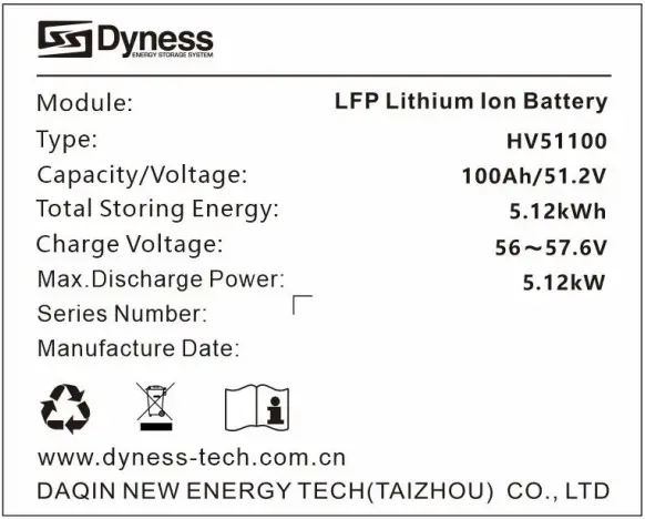
Battery voltage is higher than safe voltage, direct contact with electric shock hazard.
Be careful with your actions and be aware of the dangers.
Read the user manual before using.
The scrapped battery cannot be put in to the garbage can and must be professionally recycled.
After the battery life is terminated, the battery can continue to be used after it recycled by the professional recycling organization and do not discard it at will
Product Specification
System Performance Parameter
Table 2-1 The parameter of Power Rack HV4 system-1
Item| Power Rack
HV4 -20| Power Rack
HV4 -25| Power Rack
HV4 -30| Power Rack
HV4 -35
---|---|---|---|---
Module Type| LFP| LFP| LFP| LFP
Nominal Voltage(V)| 204.8V| 256V| 307.2V| 358.4V
Work Voltage Range(V)| 179.2-230.4| 224-288| 268.8-345.6| 313.6-403.2
Module configuration| 4 Series| 5 Series| 6 Series| 7 Series
Nominal Energy(kWh)| 20.48| 25.6| 30.72| 35.84
Nominal Power(kW)| 12.288| 15.36| 18.432| 21.504
Max Power(kW)| 20.48| 25.6| 30.72| 35.84
Charging Current(A)| 50| 50| 50| 50
Discharge Current(A)| 50| 50| 50| 50
Dimension(mm)| 6016101422| 6016101422| 6016101422| 6016101422
Weight(kg)| 237| 290.5| 344| 397.5
Battery Module Name| HV51100| HV51100| HV51100| HV51100
Battery Module Quantity(pcs)| 4| 5| 6| 7
Table 2-2 The parameter of Power Rack HV4 system-2
Item| Power Rack
HV4 -40| Power Rack
HV4 -46| Power Rack
HV4 -51| Power Rack
HV4 -56
---|---|---|---|---
Module Type| LFP| LFP| LFP| LFP
Nominal Voltage(V)| 409.6V| 460.8V| 512V| 563.2V
Work Voltage Range(V)| 358.4-460.8| 403.2-518.4| 448-576| 492.8-633.6
Module configuration| 8 Series| 9 Series| 10 Series| 11 Series
Nominal Energy(kWh)| 40.96| 46.08| 51.2| 56.32
Nominal Power(kW)| 24.576| 27.648| 30.72| 33.792
Max Power(kW)| 40.96| 46.08| 51.2| 56.32
Charging Current(A)| 50| 50| 50| 50
Discharge Current(A)| 50| 50| 50| 50
Dimension(mm)| 6016102062| 6016102062| 6016102062| 6016102062
Weight(kg)| 486| 539.5| 593| 646.5
Battery Module Name| HV51100| HV51100| HV51100| HV51100
Battery Module Quantity(pcs)| 8| 9| 10| 11
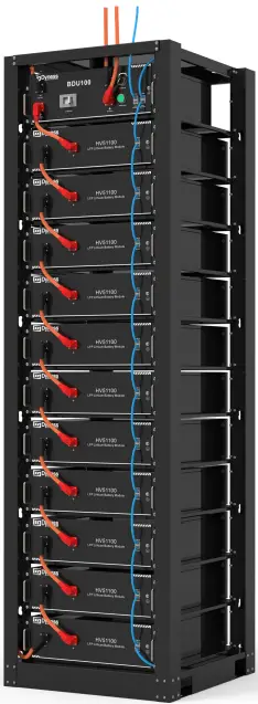
Figure2-1 Power Rack HV4-56
Battery Module
Table 2-3 Product parament
| Module Name | HV51100 |
|---|---|
| Cell Technology | Li-ion(LFP) |
| Battery Module Capacity (kWh) | 5.12 |
| Battery Module Voltage (Vdc) | 51.2 |
| Battery Module Capacity (Ah) | 100 |
| Battery Module Charge Voltage (Vdc) | 57.6 |
| Battery Module Charge Current (Normal) [A] | 50 |
| Battery Module Discharge Current (Normal) [A] | 50 |
| Dimension(WDH, mm) | 481535140 |
| Communication | CAN |
| Pollution Degree (PD) | I |
| IP Grade | IP20 |
| Weight(kg) | 43.5 |
Interface Definition
This section elaborates the interface functions of the front interface of the
device.
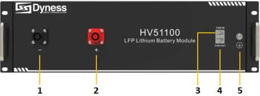
Figure2-2 The sketch of interface.
Table 2-4 Interface Definition
| Item | Name | Definition |
|---|---|---|
| 1 | Negative socket | Battery output or Serial anode cable |
| 2 | Positive socket | Battery output or Serial anode cable |
| 3 | CAN IN | RJ45 port, connect to former module or BDU |
| 4 | CAN OUT | RJ45 port, connect to next module or BDU |
| 5 | Grounding | Shell ground connection |
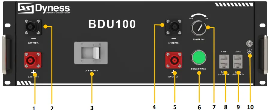
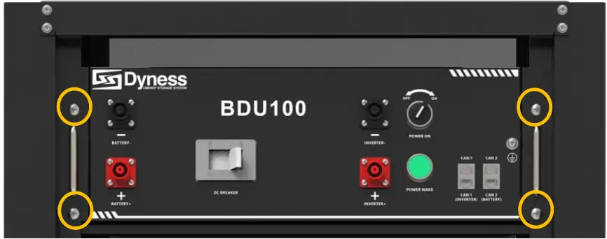
Figure2-3 The sketch of interface.
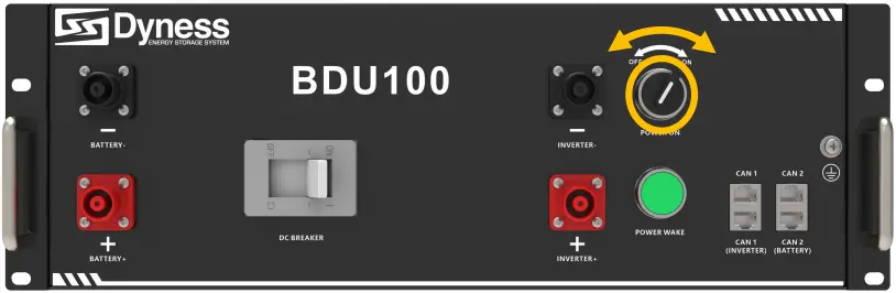
Table 2-5 Interface Definition
| Item | Name | Definition |
|---|---|---|
| 1 | Positive socket | Battery input cable |
| 2 | Negative socket | Battery input cable |
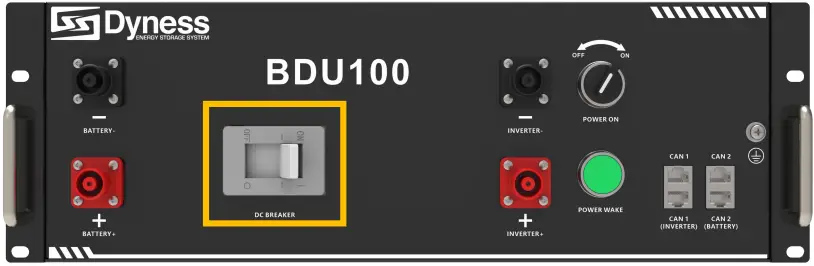
| 3 | DC Breaker | The master switch of the battery system ,you musts itch |
on it before switching on power on & power wake switch; Short circuit
protection.
4| Negative socket| Battery output cable
5| Positive socket| Battery output cable
6| Power Wake Button| Long press this button to start the battery system
7| Power On switch| Turn on the switch to power the BMS system
8| CAN 1| RJ45 communication port between the battery system and
inverter
9| CAN 2| RJ45 communication port between battery module and BDU
10| Grounding| Shell ground connection
Communication port
Figure 2-3 CAN interface definition
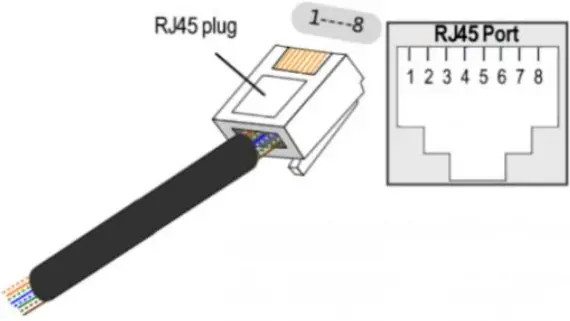
Table 2-6 BDU CAN1 Pin Definition
| Foot position | Color | Definition |
|---|---|---|
| PIN1 | Orange/white | Reserve |
| PIN2 | Orange | XGND |
| PIN3 | Green/white | Reserve |
| PIN4 | Blue | CANH |
| PIN5 | Blue/white | CANL |
| PIN6 | Green | Reserve |
| PIN7 | Brown/white | Reserve |
| PIN8 | Brown | Reserve |
Table 2-7 BDU CAN2 & Battery CAN Pin Definition
| Foot position | Color | Definition |
|---|---|---|
| PIN1 | Orange/white | WAKE |
| PIN2 | Orange | 24V+ |
| PIN3 | Green/white | 24V+ |
| PIN4 | Blue | CANSH |
| PIN5 | Blue/white | CANSL |
| PIN6 | Green | 24V- |
| PIN7 | Brown/white | 24V- |
| PIN8 | Brown | CANSG |
Battery Management System(BMS)
Voltage Protection
Low Voltage Protection in Discharging :
When any battery cell voltage or total voltage is lower than the rated
protection value during discharging, the over-discharging protection is
activated. Then battery system stops supplying power to the outside. When the
voltage of each cell back to rated return range, the protection is over.
Over Voltage Protection in Charging:
Battery will stops charging when total voltage or any battery cell voltage
reaches threated protection value during charging stage. When total voltage or
all cell back to rated range, the protection is over.
Current Protection
Over Current Protection in Charging
When the charge current is higher than the protection value, the system stops
charging. Protection is released after rated time delaying or charging current
released.
Over Current Protection in Discharging
When the discharge current is higher than the protection value, the systems to
PS discharging. Protection is released after rated time delaying or
discharging current released.
Temperature Protection
Low/Over temperature protection in charging
When battery’s temperature is beyond range of 0℃~+55℃ during charging,
temperature protection is activated, device stops charging. The protection is
over when temperature back to rated working range
Low/Over temperature protection in discharging
When battery’s temperature is beyond range of -20 ℃ ~+55 during
discharging, temperature protection is activated, device stops supplying power
to the outside. The protection is over when temperature back to rated working
range.
Caution
Battery’s maximum discharging current should be more than load’s maximum
working current
Installation and Configuration
Preparation for installation
Safety Requirement
This system can only be installed by personnel who have been trained in the
power supply system and have sufficient knowledge of the power system. The
safety regulations and local safety regulations listed below should always be
followed during the installation.
-
All circuits connected to this power system with an external voltage of less than 48V must meet the SELV requirements defined in the IEC60950 standard.
-
If operating within the power system cabinet, make sure the power system is not charged. Battery devices should also be switched off.
-
Distribution cable wiring should be reasonable and has the protective measures to avoid touching these cables while operating power equipment.
-
when installing the battery system, must wear the protective items below.
-
The isolation gloves
-
Safety goggles
-
Safety shoes
Environmental requirements
- Working temperature: -10℃ ~ +55℃
- Charging temperature range is 0℃~+55℃
- Discharging temperature range is -10℃ ~+55℃
- Storage temperature: -10℃ ~ +35℃
- Relative humidity: 5% ~ 85%RH
- Elevation: no more than 4000m
- Operating environment: Indoor installation, sites avoid the sun and no wind, nonconductive dust and corrosive gas. And the following conditions are met:
- Installation location should be away from the sea to avoid brine and high humidity environment.
- The ground for product arrangement shall be flat and level.
- There is no flammable explosive materials near to the installation site.
- The optimal ambient temperature is 15℃~ 30℃
- Keep away from dust and messy zones.
- The installation site must be equipped with fire-extinguisher system for safety purpose
Tools and data
Hardware tool
Tools and meters that may be used are shown in table 3-1
Table 3-1 Tool instrument
Name
Screwdriver Slotted Phillips)| Multimeter
Torque wrench| Clamp current meter
Diagonal pliers| Insulation tape
Pointed nose pliers| Temperature meter
Pliers to hold the wire| Anti-static bracelet
Stripping pliers| Cable tie
Electric drill| Tape measure
Technical preparation
Electrical interface check
Devices that can be connected directly to the battery can be user
equipment, power supplies, or other power supplies.
- Confirm whether the user’s PV power generation equipment, power supply or other power supply equipment has a DC output interface, and measure whether the DC power output voltage meets the voltage range requirements Table 2-1 and Table 2-2.
- Confirm that the maximum discharge current capability of the DC power interface of the user’s photovoltaic power generation equipment, power supply or other power supply equipment should be higher than the maximum charging current of the products used in Table 2-1 and Table 2-2. If the maximum discharge capacity of the DC power interface of the user’s photovoltaic power generation equipment is less than the maximum charging current of the products used in Table 2-1 and Table 2-2, the DC power interface of the user’s photovoltaic power generation equipment shall have current limiting function to ensure the normal operation of the user’s equipment.
- Verify that the maximum operating current of the battery-powered user equipment (inverter DC input) should be less than the maximum discharge current of the products used in Table 2-1 and Table 2-2.
The security check
- Firefighting equipment should be provided near the product, such as portable dry powder fire extinguisher.
- Automatic fire fighting system shall be provided for the case where necessary.
- No flammable, explosive and other dangerous materials are placed beside the battery.
Unpacking inspection
- When the equipment arrives at the installation site, loading and unloading should be carried out according to the rules and regulations, to prevent from being exposed to sun and rain.
- Before unpacking, the total number of packages shall be indicated according to the shipping list attached to each package, and the case shall be checked for good condition.
- In the process of unpacking, handle with care and protect the surface coating of the object.
- Open the package, the installation personnel should read the technical documents, verify the list, according to the configuration table and packing list, ensure objects are complete and intact, if the internal packing is damaged, should be examined and recorded in detail
Packing list of Power Rack HV4-56 is as follows:
| Item | Specification | Quantity | Figure |
|---|---|---|---|
| Battery- HV51100 | 51V/100Ah480×535×133mm | 11 | |
| BDU100 | 480×410×155mm | 1 | |
| Power cable- positive | Red/35mm²/L3000mm | 1 | |
| Power cable- negative | Black/35mm²/L3000mm | 1 | |
| Serial cable | Orange/35mm²/L215mm | 10 | |
| Module cable- positive | Orange/35mm²/L215mm | 1 | |
| Module cable- negative | Orange/35mm²/L2200mm | 1 | |
| Communication parallel cable | Black/L350mm/Double RJ45 plug | 12 |

Communication cable-to inverter| Black/L3000mm/Double RJ45 plug| 1|
Communication Bottom module to BDU CAN2 IN| Black/L2200mm/Double RJ45 plug| 1|
Ground wire| L3000mm,4mm²| 1|
User Manual| Power Rack HV4 User manual| 1|
Screw| Combination screws M6*14| 60|
CAN resistor| 120Ω| 1|
Engineering coordination
Attention should be paid to the following items before construction:
- Power line specification. The power line specification shall meet the requirements of maximum discharge current for each product.
- Mounting space and bearing capacity. Make sure that the battery has enough room to install, and that the battery rack and bracket have enough load capacity.
- Wiring. Make sure the power line and ground wire are reasonable. Not easy to short- circuit, water and corrosion.
Equipment installation
Table 3-2 Installation steps
Step 1| Mechanical installation| 1.Battery placement position
determination
---|---|---
2.Battery module installation
| | 3.BDU installation
---|---|---
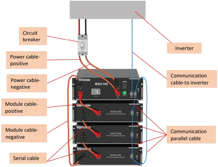
Step3| Electrical installation| 1.Ground cable installation
2.Battery module serial cable installation
3.Connect the module cable-positive from the battery“+” to the BDU “+”
4.Connect the module cable-negative from the battery “-” to the BDU “-”
5. Connect the CAN 2 of the BDU with the CAN IN of the battery module with
the communication parallel cable, then connect the CAN OUT of the previous
battery module with the CAN IN of the next battery module in turn, and finally
connect the CAN 2 of the BDU with the communication parallel cable Connectto
the CAN OUT of the bottom battery module
Step4| Battery system self-test| 1.Turn the BDU ‘DC Breaker’ ON/OFF
switch to the “ON” state
2.Turn the ‘Power ON’ ON/OFF switch to the “ON”state
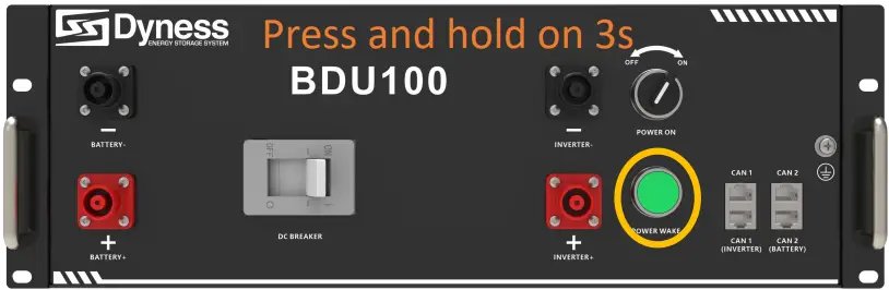
3.Press ‘POWER WAKE’ button 3S to wake up battery
4.Check the system output voltage and ‘POWER WAKE’ led status
5. Shut down the system
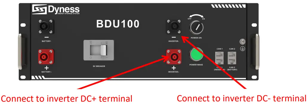
Step5| Connecting inverter| 1.Connect total positive & total negative
cable of the battery system to the inverter
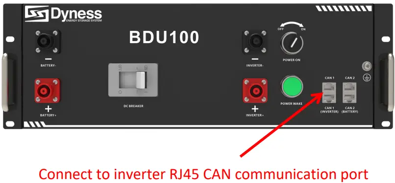
2.Connect the communication cable from the masterCAN 1 to the inverter
3.Close the DC breaker
4.Turn on the ‘Power ON’ switch , wake up system by ‘POWER WAKE’ button
5.Turn on the inverter and check the communication between inverter and
battery system
Installation preparation
- Make sure the environment is meeting all technical requirements: “3.1.1”
- Prepare equipment and tools for installation.
- Confirm that the DC breaker is in the OFF state to ensure that it is no live operation.
Mechanical installation
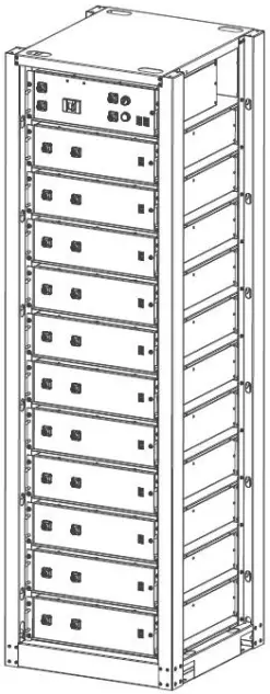
Installation method:
-
Place the HV51100 unit on the rack bracket as shown in the figure and push the device into the rack at the installation position. (The rack structure in the figure is for reference only)
-
Secure the HV51100 unit to the rack with a nut through the mounting holes top on the hanging ears of the HV51100 unit.
-
Insert the second one HV51100 in to the rack.
-
Stack the required number of battery and BDU as described above, and use 4 screws to fix the battery and BDU on the front bracket. Shown as Figure3-5.
Electrical installation
Before connecting the power cables, use multimeter to measure cable continuity, short circuit, confirm positive and negative, and accurately mark the cable labels. Measuring methods:
- Power cable check: select the buzzer mode of multimeter and detect the both ends of the same color cable. If the buzzer calls, it means the cable is in good condition.
- Short circuit judgment: choose multimeter resistor file, probe the same end of positive and negative pole, if the resistor shows infinity, means that the cables available.
- After visual testing of power line connection, the positive and negative poles of the battery shall be connected respectively to the positive and negative poles of the opposite terminal.
It is better to add a circuit breaker between the inverter and the battery system.
Battery system self-test
-
Switch the DC BREAKER of BDU to the “ON” state

-
Switch on the “POWER ON” switch
-
Press the “POWER WAKE” button for about 3S. The system start-up.
-
Use a multimeter to measure the output voltage on the positive and negative
ports of the BDU. Confirm the voltage is within the normal range -
The output voltage should conform to the voltage range in the table “Table 2-1/2The parameter of Power Rack HV4 system”. Otherwise, the system will be not working properly.
Danger: The voltage of the battery is too high, please pay attention to do self-protection during the measurement.
Shut down the system
-
Switch off the “POWER ON” switch

-
Switch the BDU “DC BREAKER” to the “OFF” state .
Connecting inverter
Caution: A external DC Breaker that operates both positive and negative conductors simultaneously between the BDU and inverter on the power cable is recommended. After waking up the BDU and ensure that the BDU is pre-charged, you can turn on it.
Danger:
Please confirm that the battery system is in the off state before connecting.
It may cause electric shock to personnel and damage to the inverter if connect
the battery directly without power off. Connect the positive and negative
connectors with the positive and negative power lines together. Both ends
must have connectors, and the connector on the inverter side is provided by
the inverter. If that 2m power cable is not long enough, please find another
power cable of the same specification, the length cannot be longer than 3m.
-
Connect External Power Cable to the inverter;
-
Connect the INVERTER-CAN communication cable to the inverter RJ45 CAN port.
Warning:
Double check all the power cables and communication cable. Make sure the
voltage of the Inverter is in the same level with the battery system.
- Switch on the inverter, to make sure all the power equipment can work normally.
- Start the battery system. Referring to the section“3.2.4”.
Register on the website after installation
After the battery system installation is completed and the running is normal,
you need to log in to the DYNESS official website to register the product
installation and use information to make the product warranty effective.
Please follow the instructions on the website to register. http://www.dyness-
tech.com.cn Service Sign Up
Maintenance
Trouble shooting
Danger: The Power Rack HV4 battery system is a high voltage DC system,
operated by professional and authorized person only.
Danger : Before check the failure, must check all the cables connection.
Switches airtight or not (refer to section 3.2.4), and if the battery system
can be woken up normally.
| No | Problem | Possible Reason | Solution |
|---|---|---|---|
| 1 | The battery has no voltage output, and “POWER ON”/ “POWER WAKE” | ||
| Lights off. | The DC breaker of the BDU didn’t be turned on | Turn on the DC |
breaker of BDU
2| The “POWER ON” switch of the BDU box was not switched on| Switch on
the “POWER ON” button
3| Battery is in sleep state.| Long press the “POWER WAKE” button for
about3S
4| The fuse in the BDU box is faulty| Replace fuse
5| Battery gets into over- discharged protection| Charge the battery to
relieve the protection state
6
| The battery has no voltage output, but “POWER ON”/ “POWER WAKE” arson| The
relay in BDU is faulty| Replace a new BDU directly
7| When the battery is connected to the inverter, the DC breaker trips
automatically| The circuit between the battery and the inverter has a short
circuit point| Check whether there is a short circuit in the circuit between
the battery and the inverter Check if the inverter is faulty
8| Communication failure between battery and inverter| The wrong battery
model type is selected on the inverter| Select correct battery model type on
the inverter
Replacement of main component
Danger: The Power Rack HV4 battery system is a high voltage DC system, only can be operated by professional and authorized person.
Replacement of Battery Controller (BDU)
Turn off the whole battery system. Ensure the Negative terminal and
Positive terminal have no power. The shutdown progress refers to section 3.2.5
Remove the four screws on the BDU and remove the BDU from the system.
Change a new BDU. Then fix four screws
Battery Maintenance
Danger: The maintenance of battery only can be operated by professional
and authorized person.
Danger: you need turn off the battery system firstly when you do some
maintenance items.
Voltage Inspection:
[Periodical Maintenance] Check the voltage of battery system through the monitor software. Check whether the system voltage is normal or not. For example: Check Singlecell’s voltage is out of rated range or not.
Voltage Inspection:
[Periodical Maintenance] Check the SOC of battery system through the
monitor software. Check the SOC of battery string is normal or not.
Cables Inspection:
[Periodical Maintenance] Visual inspect all the cables of battery system.
Check the
cables have broken, aging, getting loose or not.
Balancing:
[Periodical Maintenance] The battery system will become unbalanced if
have not be charged fully for a long time. Solution: Preform the balancing
maintenance (fully charged) every 3 month. Generally, this maintenance
progress needs to be completed when external devices such as the monitor
software and battery and inverter are in good communication.
Output Relay Inspection :
[Periodical Maintenance] Under low load condition (low current), control
the output relay OFF and ON to hear the relay has click voice, that’s mean
this relay can off Andon normally
Storage Recommendations
- For long-term storage (more than 3 months), the battery cells should be stored in the environment: temperature range of 5~45℃, relative humidity <65%and contains non- corrosive gas .
- The battery module should arranged in range of 5~45℃, dry, clean and well ventilated environment. The battery should be charged to 50~55% SOC before storage.
- It is recommended to active the battery system (discharge and charge) every 3 months, and the longest duration of storage without charge and discharge cannot exceed 6 months.
Caution: The cycle life of the battery will have relative heavily reduction if not follow the above instructions to store the battery for a long term.
Shipment
Battery module will pre-charged to 50% SOC or according to customer requirement before shipment. The remaining capacity of battery cell is determined by the storage time and condition after shipment.
- The battery modules meet the UN38.3 certificate standard.
- In particular, special rules for the carriage of goods on the road and the current dangerous goods law, specifically ADR (European Convention on the International Carriage of Dangerous Goods by Road), as amended, must be observed.
Daqing New Energy Tech (Taizhou) Co., Ltd. Address: Building 13, Kunshan
Jiangnan Industrial Park, Chanchiang West Road, Jiangnan District, Taizhou
City, Jiangsu Province, China, 225500.
Email: Sales@dyness-tech.com
Website: www.dyness-tech.com.cn

Read User Manual Online (PDF format)
Read User Manual Online (PDF format) >>