S006000000131 Roxtec Rectangular Systems Instruction Manual
- June 13, 2024
- ROXTEC
Table of Contents
**S006000000131 Roxtec Rectangular Systems Instruction Manual
**
Components
-
Roxtec Wedge

-
Roxtec Stayplate

-
Roxtec RM module

-
Roxtec Lubricant
Tools
-
Spanner 13 mm (not included)
-
Brush (not included)

-
Roxtec tools (not included)
Frame installation
Attach the frame to the structure in line with Roxtec guideline documents.

Note
- For optimum reliability, wait 24 hours or longer after installation before exposing the cables/pipes to strain or pressure.
- Cables/pipes shall be parallel to the frame.
- Cable/pipe with a considerable weight needs to be supported to prevent damage or subsidence to the seal.
- Approvals or certificates may include amendments or limitations related to this application.
- A module with core is spare capacity.
- Placing spare capacity modules close to the wedge is recommended.
- The latest version of this and related documents such as translations, are found at roxtec.com.
- Partially installed openings shall be compressed if left unattended.
After installation inspection
- Are all modules secured by stayplates?
- Are the wedge screws tightened and the wedge clip attached?
- Is there visible protruding lubricant?
- Are there stayplates between every module row?
- Is the wedge correctly oriented ?
- Is the combined height of modules correct according to frame packing height?
Disassembly
-
Untighten the screws alternately to full stop. Do not exceed 20 Nm.

-
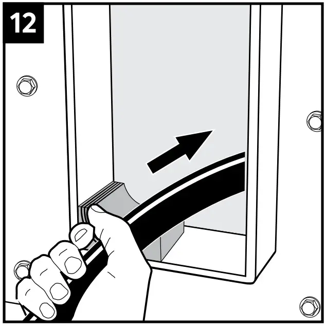
Remove the wedge by lifting it over the stayplate using a flat tool.

-
Remove the modules required.

-
Keep the module rows sorted until reinstallation. If a module needs to be replaced, all modules in that row must be replaced.

Reinstallation
-
Clean the exposed sealing surfaces.

-
Lubricate the exposed sealing surfaces.

-
Lubricate the corners thoroughly.

-
Partially installed openings shall be compressed if left unattended. Excess lubricant is a sign of good compression.

Installation
-
Clean the aperture.

-
Lubricate the sealing surfaces of the frame. Lubricate the corners thoroughly

-
Achieve a 0.1-1.0 mm (A) gap between the two module halves when held against the cable/pipe.

-
Adapt the modules by peeling off layers.

-
The number of layers may not differ (A) by more than one between the corresponding module halves.

-
Lubricate the sealing surfaces with Roxtec Lubricant.

-
Lubricate the sealing surfaces of any spare module. Do not removethe core.

-
Lubricate solid modules on the sealing surfaces.

-
Measure your frame height (H). This decides your packing height (h).

-
The combined height of the modules must correspond to the packing height (h). Consider your packing
plan.

S= frame size.
w= frame width. -
Insert a module half.

-
Insert a cable.
-
Cables shall go parallel to the frame.

-
Continue to fill the transit considering your packning plan.

-
Insert a stayplate between every row of modules.

-
Ensure that the modules (A) are secured within the stayplate edges (B).

-
Before inserting the final row of modules, insert two stayplates.

-
Separate the two stayplates and insert the final row of modules between the stayplates.

-
A Roxtec pre-compression tool can be used to make room for the wedge, if necessary

-
Lubricate the indicated areas of the wedge.

-
Correctly orientate the wedge according to the markings.

-
Insert the wedge so the stop flange (A) is in contact with the frame (B).

-
The wedge can be placed anywhere in the frame, not just at the top

-
Tighten the screws alternately until full mechanical stop, max 20 Nm. Protruding excess lubricant indicates a tight sea
-
Attach the wedge clip to the wedge screws to complete the installation.

-
Check additional documentation, if applicable

Disclaimer
The Roxtec cable and pipe entry sealing system (‘the Roxtec system’) is a
modular-based system of sealing products consisting of different components.
Each and every one of the components is necessary for the best performance of
the Roxtec system. The Roxtec system has been certified to resist a number of
different hazards. Any such certification, and the ability of the Roxtec
system to resist such hazards, is dependent on all components that are
installed as a part of the Roxtec system. Thus, the certification is not valid
and does not apply unless all components installed as part of the Roxtec
system are manufactured by or under license from Roxtec (‘authorized
manufacturer’). Roxtec gives no performance guarantee with respect to the
Roxtec system, unless (I) all components installed as part of the Roxtec
system are manufactured by an authorized manufacturer and (II) the purchaser
is in compliance with (a), and (b), below. (a) During storage, the Roxtec
system or part thereof, shall be kept indoors in its original packaging at
room temperature. (b) Installation shall be carried out in accordance with
Roxtec installation instructions in effect from time to time. The product
information provided by Roxtec does not release the purchaser of the Roxtec
system, or part thereof, from the obligation to independent determine the
suitability of the products for the intended process, installation and/or use.
Roxtec gives no guarantee for the Roxtec system or any part thereof and
assumes no liability for any loss or damage whatsoever, whether direct,
indirect, consequential, loss of profit or otherwise, occurred or caused by
the Roxtec systems or installations containing components not manufactured by
an authorized manufacturer and/or occurred or caused by the use of the Roxtec
system in a manner or for an application other than for which the Roxtec
system was designed or intended. Roxtec expressly excludes any implied
warranties of merchantability and fitness for a particular purpose and all
other express or implied representations and warranties provided by statute or
common law. User determines suitability of the Roxtec system for intended use
and assumes all risk and liability in connection therewith. In no event shall
Roxtec be liable for indirect, consequential, punitive, special, exemplary or
incidental damages or losses. The Roxtec products are offered and sold in
accordance with the conditions of the Roxtec General Terms of Sales. The
latest version of the Roxtec General Terms of Sales can be found and
downloaded from roxtec.com/ general-terms-of-sales.”
Roxtec International AB Box 540, 371 23 Karlskrona, SWEDEN +46 455 36 67 00,
info@roxtec.com
www.roxtec.com

References
- Sealing solutions for cables and pipes | Roxtec Global
- Sealing solutions for cables and pipes | Roxtec Global
- Sealing solutions for cables and pipes | Roxtec Global
Read User Manual Online (PDF format)
Read User Manual Online (PDF format) >>