Hynetek RD-2010 EVB_HUSB238_002DD Evaluation Board User Guide
- June 4, 2024
- Hynetek
Table of Contents
Hynetek RD-2010 EVB_HUSB238_002DD Evaluation Board

FEATURES
- USB Power Delivery (PD) sink-only power role
- Support charging of 1 to 4 cell batteries
- Support type-C 1.4 & USB PD3.0 version 1.3
- External resistor to set the target RDO
- Flexible monitoring and configuration via I 2 C interface
APPLICATIONS
- Power tools
- Smart speakers
- Portable electronics
- Internet of Things (IoT) devices
- Handsets
- Wireless chargers
- Industrial applications
GENERAL DESCRIPTION
The HUSB238 is a highly integrated USB Power Delivery (PD) controller as sink role. The HUSB238 is compatible with USB PD3.0 V1.3 and Type-C V1.4. And it can also support charge protocols such as Apple divider 3, BC1.2 SDP, CDP and DCP. The HUSB238 can be used in electronic devices that have legacy barrel connectors (called Barrel Connector Replacement) or USB micro-B connectors. The applications can be wireless chargers, IoT (Internet of Things) devices, drones, smart speakers, power tools, and other rechargeable devices. The HUSB238 is available in 3 mm x 3 mm DFN-10L package and 3.9mm x 4 mm SOT33-6L package.
APPLICATION BLOCK DIAGRAM AND EVB FIGURE

INTRODUCTION
INTERFACE SPECIFICATIONS
There are three interfaces on this evaluation board. The following table
describes the functions of each interface.
| Interfaces | Descriptions |
|---|---|
| USB type-C receptacle | Connect to a standard USB PD power |
adaptor(≤100W)through a USB type-C cable
Power output| One Fixed PDO output of PD power adaptor(Output voltage can be
set by an external
2
resistor RVSET or I C interface)
I2C interface| Optional interface for advanced monitoring and programming
NOTES FOR THE EVALUATION DESIGN BOARD
The RDO of HUSB238 default factory setting is 20V3.25A. If the USB Type-C
cable does not have an eMarker chip or the eMarker indicates the cable current
rating being only 3A, the maximum current rating of source capability of the
PD power adapter is only 3A and the PD power adapter will fail to match the
HUSB238. In this situation, the request current can be set to 3A (or smaller)
by changing the external resistor RISET to 22kΩ (or smaller).
| Items | Specifications | Functions | Notes |
|---|---|---|---|
| Q1 | Can be a single PMOS, back-to-back double PMOS or an integrated |
load switch
| 1. VBUS UVP/OVP protections
2. Control the VOUT power-up timing and soft start time
3. Prevention of current flowing backward
| Q1 is optional, short J2 jumper for simple design. Q1, R2 and R3 are not
connected.
ZD1, ZD2, ZD3, ZD4| NC TVS SOD-323| Enhance the chip ESD capability| Optional
RVSET| NC 0603 1% Resistor| Default RDO with 20V| See the recommended resistor
list
RISET| NC 0603 1% Resistor| Default RDO with 3.25A| See the recommended
resistor list
CIRCUIT CONNECTION
The circuit connection of HUSB238 evaluation board with the PD power adapter
and powered device is shown as Figure 1.
VOLTAGE AND CURRENT REQUEST PRINCIPLE
- HUSB238 supports three kinds of voltage and current request methods:
- Factory defaults settings (Default request voltage and current is 20V3.25A, custom design is also allowed).
- VSET & ISET pins dynamic setting of the targeted voltage and current by changing of the RVSET and/or RISET resistors connected to the VSET & ISET pins separately.
- I 2 C advanced setting.
- The voltage and current of HUSB238 actually request is the lower of factory defaults setting and the VSET/ISET pins setting.
- For example, if factory default request voltage is 20V, the VSET pin request voltage is 12V, the actual request voltage is 12V.
- For example, if factory default request current is 2A, the ISET pin request current is 3A, and the actual request current is 2A.
- I 2 C advanced setting has the highest priority, it can bypass the above two kinds of settings:
- HUSB238 stores source capability received from the USB PD power adapter. It includes all FPDOs data and other information sent from the USB PD power adapter. The MCU can choose the proper PDO according to this information.
- It is suggested the VEST pin be shorted to ground such that the default request voltage 5V. Then the MCU request the actual required voltage & current through the I2 C interface.
- Matching mechanism.
- Only the voltage and current of the PD source meet the both conditions, it can be matched.
- Request voltage value must less-than or equal-to Source PDO voltage value.
- Request current value must less-than or equal-to Source PDO current value.
- If the conditions are not matched, according to the HUSB238 mismatch rules, you can choose:
- Look down for a lower voltage for matching. For example, HUSB238 requests 60W 20V3A, but the PD source provides 45W with PDOs of 5V3A, 9V3A, 12V3A, 15V3A and 20V2.25A. The 20V2.25A PDO fails to match, while the 15V3A PDO matches.
- Request 5V PDO directly.
RECOMMEND RVSET & RISET RESISTOR VALUE LIST
The relationship of RVSET value and the request voltage:
The relationship of RISET value and the request current:
The target voltage and current are dynamically applied by changing the value
of RVSET and RISET.
DESIGN OVERVIEW
BLOCK DIAGRAM
KEY PRODUCTS
HUSB238 – USB PD Sink Controller
Key features of HUSB238:
- USB-IF certified PD sink controller with TID 3666
- 3mm x 3mm DFN-10L and 3.9mm x 4.0mm SOT33-6L packages options
- Support type-C 1.4 & USB PD3.0 version 1.3
- Support legacy charging sink, BC1.2 SDP, CDP & DCP detection, Apple Divider 3 detection
- 3.0V to 25V operation range
- 30V voltage rating on VBUS, GATE pins, and 25V voltage rating on CC1, CC2 pins
- External resistor to set the target RDO voltage and current
- I 2 C interface access for advanced PDO request
- eMarker emulator for cable application with output current>3A
- Integrated load switch gate drivers (PMOS)
- VBUS over-voltage (OVP) and under-voltage (UVP) protection
- OTP protection, over-temperature protection with configurable thresholds
- Low power consumption
- Operating temperature -40 °C to 125 °C
TEST RESULT
TEST CONDITIONS
Room temperature test condition.
- Input: 65W or above USB PD power adapter.
- Output: DC 5V to 20V.
TEST EQUIPMENTS
Oscilloscope Tektronix MDO3024, Lenovo 65W USB PD power adapter, multi-meter.
I 2 C interface monitoring requires additional equipment, including: a
computer with USB interface, USB data lines, Total Phase Aardvark I2C/SPI Host
Adapter, and Total Phase software USB_V2.16.exe.
TEST SETTING
Figure 5. shows a Lenovo 65W USB PD power adapter connected to the HUSB238
evaluation board to output 20V. The request voltage is set by the RVSET
resistor.
Figure 6. shows the dynamic voltage request through I 2 C interface. The
source capabilities information of the Lenovo 65W USB PD power adapter can be
read through I 2 C interface.

TEST PROCESS
Test item 1, request PDO through external resistor:
- Connect the Lenovo 65W USB PD power adapter output to EVB_HUSB238_002DD with a USBC Type-C to USB Type-C cable.
- Power on the 65W USB PD power adapter, use a multi-meter to measure the voltage between VBUS pad and ground in the EVB_HUSB238_002DD.
- Change the RVSET resistor value in the EVB_HUSB238_002DD, check the change of the output voltage. Test item 2, request PDO through the I2C interface:
- Connect the computer to the Total Phase Aardvark I2C/SPI Host Adapter with the USB data cable, connect the I2C interface of the EVB_HUSB238_002DD to the Total Phase Aardvark I2C/SPI Host Adapter. And run the I2C software on the computer.
- Select device address 0x08 to open the HUSB238 register map in the I2C software. Then select the target register address. Click on “Read” button to read the specified register value. Click on “Write” button to write a value to the specified register.
- Capture the waveforms shown in Figure 8. and Figure 9.
TEST WAVEFORMS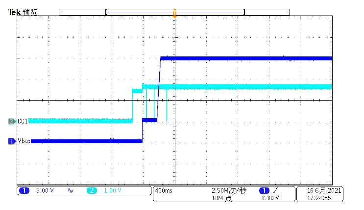

DESIGN DOCUMENTS
SCHEMATIC
BOM LIST
EVB_HUSB238_002DD BOM
No.| Material Name| Specification Description| Item|
pcs| Remark
Plug-in Part
1| Resistor| 10Ω 0603 5%| R1| 1|
2| Resistor| 30KΩ 0603 5%| R2| 1|
3| Resistor| 100KΩ 0603 5%| R3| 1|
4| Resistor| NC 0603 1%| RVSET| NC|
5| Resistor| NC 0603 1%| RISET| NC|
6| capacitor| 330P50V X7R 0603| C2.3| 2|
7| capacitor| 105K50V X7R 0603| C1| 1|
8| TVS diode| NC TVS SOD-323| ZD1.2.3.4| NC|
9| MOSFET| AD30P47D3 P-MOS DFN3*3| Q1| 1|
10| IC| HUSB238_002DD-DFN-10L| U1| 1|
11| Jumper| NC| J2| NC|
12| Connector| USB3.1 Type-C Receptacle 16PF SMT| J1| 1|
PCB LAYOUT

IMPORTANT NOTICE
- Hynetek Semiconductor Co., Ltd. and its subsidiaries (Hynetek) reserve the right to make corrections, enhancements, improvements and other changes to its semiconductor products and services per JESD46, latest issue, and to discontinue any product or service per JESD48, latest issue. Buyers should obtain the latest relevant information before placing orders and should verify that such information is current and complete. All semiconductor products (also referred to herein as “components”) are sold subject to Hynetek’s terms and conditions of sale supplied at the time of order acknowledgment.
- Hynetek warrants performance of its components to the specifications applicable at the time of sale, in accordance with the warranty in Hynetek’s terms and conditions of sale of semiconductor products. Testing and other quality control techniques are used to the extent Hynetek deems necessary to support this warranty. Except where mandated by applicable law, testing of all parameters of each component is not necessarily performed. Hynetek assumes no liability for applications assistance or the design of Buyers’ products. Buyers are responsible for their products and applications using Hynetek components. To minimize the risks associated with Buyers’ products and applications, Buyers should provide adequate design and operating safeguards.
- Hynetek does not warrant or represent that any license, either express or implied, is granted under any patent right, copyright, mask work right, or other intellectual property right relating to any combination, machine, or process in which Hynetek components or services are used. Information published by Hynetek regarding third-party products or services does not constitute a license to use such products or services or a warranty or endorsement thereof. Use of such information may require a license from a third party under the patents or other intellectual property of the third party, or a license from Hynetek under the patents or other intellectual property of Hynetek.
- Reproduction of significant portions of Hynetek information in Hynetek data books or data sheets is permissible only if reproduction is without alteration and is accompanied by all associated warranties, conditions, limitations, and notices. Hynetek is not responsible or liable for such altered documentation. Information of third parties may be subject to additional restrictions.
- Resale of Hynetek components or services with statements different from or beyond the parameters stated by Hynetek for that component or service voids all express and any implied warranties for the associated Hynetek component or service and is an unfair and deceptive business practice. Hynetek is not responsible or liable for any such statements.
- Buyer acknowledges and agrees that it is solely responsible for compliance with all legal, regulatory and safety-related requirements concerning its products, and any use of Hynetek components in its applications, notwithstanding any applications-related information or support that may be provided by Hynetek. Buyer represents and agrees that it has all the necessary expertise to create and implement safeguards which anticipate dangerous consequences of failures, monitor failures and their consequences, lessen the likelihood of failures that might cause harm and take appropriate remedial actions. Buyer will fully indemnify Hynetek and its representatives against any damages arising out of the use of any Hynetek components in safety-critical applications.
- In some cases, Hynetek components may be promoted specifically to facilitate safety-related applications. With such components, Hynetek’s goal is to help enable customers to design and create their own end-product solutions that meet applicable functional safety standards and requirements. Nonetheless, such components are subject to these terms.
- No Hynetek components are authorized for use in FDA Class III (or similar life-critical medical equipment) unless authorized officers of the parties have executed a special agreement specifically governing such use.
- Only those Hynetek components which Hynetek has specifically designated as military grade or “enhanced plastic” are designed and intended for use in military/aerospace applications or environments. Buyer acknowledges and agrees that any military or aerospace use of Hynetek components which have not been so designated is solely at the Buyer’s risk, and that Buyer is solely responsible for compliance with all legal and regulatory requirements in connection with such use.
- Hynetek has specifically designated certain components as meeting ISO/TS16949 requirements, mainly for automotive use. In any case of use of nondesignated products, Hynetek will not be responsible for any failure to meet ISO/TS16949. Please refer to below URL for other products and solutions of Hynetek Semiconductor Co., Ltd.
©2020 Hynetek Semiconductor Co., Ltd. All rights reserved.
Trademarks and registered trademarks are the property of their respective
owners.
www.hynetek.com
References
Read User Manual Online (PDF format)
Read User Manual Online (PDF format) >>