nslusa LTSPRO 3 Color Temperature LED Task Light Instruction Manual
- June 12, 2024
- nslusa
Table of Contents
nslusa LTSPRO 3 Color Temperature LED Task Light Instruction Manual

Applications
- Under cabinet task light
- Work stations
- Over cabinet accent light
- Display cases and exhibits
- Merchandising
- Wall units and bars
COMPONENTS
-
LED Under Cabinet Light
-
1-6″ Power Cord
-
End-to-End Connector
-
Jumper cable
-
Romex connector
-
2 – Wood mounting screws
OPTIONAL

Hardwire junction box for LTSPRO fixtures, that allows for direct wiring
installation, eliminating the visible household wiring.
Junction box installation:
- Remove the junction box cover by unscrewing the mounting screws.
- Through the junction box knockout, bring in 120V power wiring. Secure it to junction box with appropriate strain relief. Strip 1/3″ (8mm) of the insulation off each incoming 120V power wire. Connect white wire (neutral) to push-in connector on white wire from junction box. Connect black incoming 120V power wire (hot wire) to push-in connector on black wire from junction box. Connect ground wire to push-in connector from ground wire of the junction box. Push all wires firmly down into connectors, so that uninsulated wire is not exposed.
- Position the junction box on the mounting surface within 6″ of the LTSPRO fixture, and drive the two mounting screws into underside of cabinet using a screwdriver or driver bit.
- Replace the junction box cover and secure it in place using the two mounting screws.
- Connect the female end of the jumper cable to the male input connector of the LTSPRO fixture.
- Connect the male end of the jumper cable to the female output connector of the junction box.
- Turn ON the ON/OFF switch from the junction box.
WARNING AND CAUTIONS
WARNING: These products may represent a possible shock or fire hazard if improperly installed or attached in any way. Products should be installed in accordance with these instructions, current electrical codes and/or the current National Electric Code (NEC).
WARNING: To avoid electric shock, disconnect power prior to installation.
CAUTION: Injury to persons and damage to the fixture and/or mounting
surface may result if the fixture is pulled from the surface. To reduce the
likelihood of such injury or damage, mount on a surface that is mechanically
sound. Suitable for indoor dry locations only.
WARNING! RISK OF FIRE: Keep fixtures away from curtains and other
combustible materials.
NOTE: Linkable up to 400 watts.
OPERATION NOTE: In order to change color temperatures, move slider in one of the 3 positions: Warm White — Neutral White — Cool White.
INSTALLATION WITH POWER CORD
If using a power cord, follow steps 1 and 2 below. If installing for hardwire power input, please skip to next section.
- Position fixture in desired location and use a Phillips screwdriver or driver bit to tighten captive mounting screws and secure fixture to an appropriate mounting surface.
- Insert power cord into “INPUT” port of fixture until fully seated.
HARDWIRE CONNECTION VIA REAR ACCESS DOOR
The rear access door is located < the in the housing middle and of it the has
back its own of / = Al X knockout for quick connection to supply wires,
eliminating the need to remove the lens cover and open the wiring compartment.
See Figure 1, then proceed to the corresponding section below.

-
Remove knockout using a hammer or punch; then loosen screw that secures rear access door using a Phillips screwdriver or driver bit. See Figure 2.

Punch out knockout, then remove screw that secures rear access door. -
Install cable connector that is appropriate for the supply wire following National Electric Code and local codes through this knockout on the access door. See Figure 3. (Use minimum 14AWG solid copper wires. 120V line voltage circuit should be protected by fuse or circuit breaker).

-
Strip back jacket on supply wires 3/8″ and use push-in wire connectors inside housing to connect wires (Black to Black/Hot, White to White/Neutral and Yellow/Green stripe [Ground] to bare wire) through knockoutso that push-in connectors are positioned on the housing side of the access door. See Figure 4

-
Replace rear access door and L secure it with screw. Note: Be sure that the wires are not NOTE: When interconnecting multiple fixtures, the first fixture MUST be powered from the right side (INPUT), and the output should be connected to the next fixture by either in-line connector or jumper cable, as shown in Figure 8. The INPUT and OUTPUT ports are clearly marked at both ends of the fixture. Gd @ Figures pinched or damaged by any part of the housing or the cover. See Figure 5.

Mounting Fixture:
- Position fixture in desired location and use a Phillips screwdriver or driver bit to tighten captive mounting screws and secure fixture to an appropriate mounting surface.
AVAILABLE ACCESSORIES (sold separately)
Interconnect cables:
12″, 18″, 24″ and 32″ flexible jumper cables; Black or White
Power cord:
6 length, grounded (3-prong) plug; Black or White
INTERCONNECTING FIXTURES
Use jumper cables to interconnect nearby fixture. See Figure 6.

Use inline connector supplied to connect fixtures directly to each other. See
Figure 7.

NOTE: When interconnecting multiple fixtures, the first fixture MUST be
powered from the right side (INPUT), and the output should be connected to the
next fixture by either in-line connector or jumper cable, as shown in Figure
8. The INPUT and OUTPUT ports are clearly marked at both ends of the fixture.

Additional Safety Measures:
Do not look directly at LED light source.
- Do not touch the LEDs.
- Do not operate without end connector cover(s) in place for any molex ports/connectors not in use.
- There are no serviceable parts inside LED module.
- Suitable for indoor dry locations only.
- This product is suitable for use in dimming circuits. For best results (5-100% lighting control), use Lutron DV60OP, S600, DVCL-153P or TC-600P type dimmers (www.lutron.com).
HARDWIRE CONNECTION VIA VIA HOUSING KNOCKOUTS
NOTE: This type of installation is less common — only done when access door cannot be used.
-
Open wiring compartment by removing screws at each end and liting cover from housing body. See Figure 9.

-
Punch out whichever knockout is best suited for connection to 120V supply wires. Knockouts are located along back and topof housing. See Figure 10.
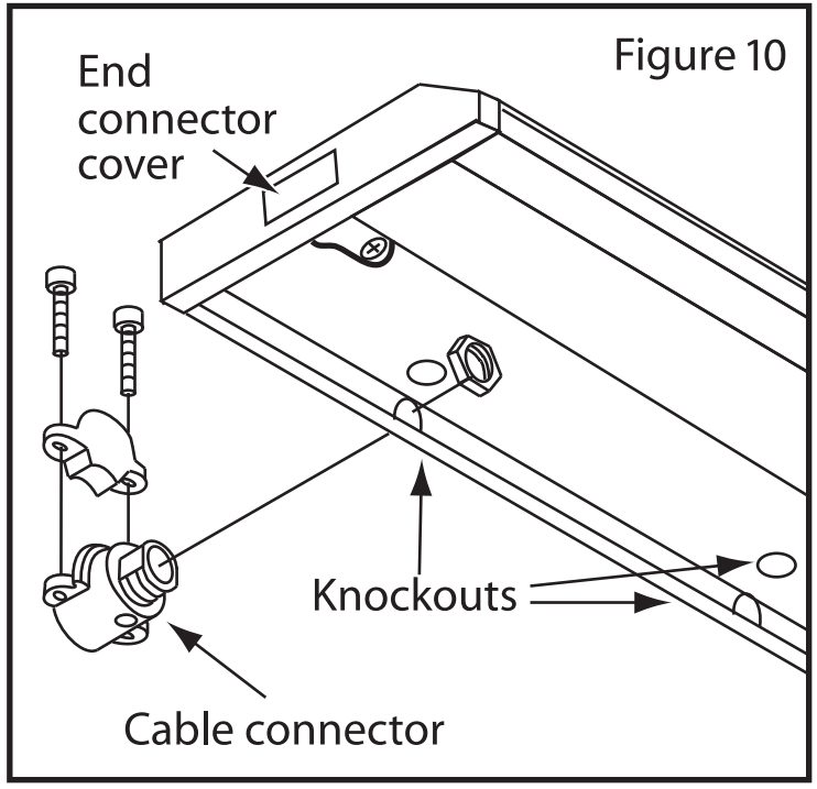
- Install cable connector and connect fixture wires following National Electric Code and/or local building code requirements. Use minimum 14AWG solid copper wires. 120V line
- voltage circuit should be protected by fuse or circuit breaker.
- Attach line voltage AC supply wires to fixture lead wires: Black to Black/Hot, White to White/Neutral and Yellow/Green (Ground) to Green or bare wire inside the fixture. Secure each connection using push-in wire connectors provided on the fixture lead wire. If your system has no ground wire, consult a qualified electrician before proceeding with the installation. NOTE: Electric shock, overheating, low or no light output and shortened fixture life can result if proper grounding is not done.
- Replace the wiring compartment cover, securing it with the existing retaining screws. NOTE: Be sure that the wires are not pinched or damaged by any part of the housing or the cover.
- Follow directions on the previous page for mounting the fixture.
- Use the screwdriver to lock the screw tightly and cover Lock the screws. the plastic cap. See Figure 11


Documents / Resources
|
nslusa LTSPRO 3 Color Temperature LED Task
Light
[pdf] Instruction Manual
LTSPRO 3 Color Temperature LED Task Light, LTSPRO, 3 Color Temperature LED
Task Light, Temperature LED Task Light, LED Task Light, Task Light
---|---
Read User Manual Online (PDF format)
Read User Manual Online (PDF format) >>