TowiTek 2564484 433MHz 4 Channel Radio Receiver Set Instruction Manual
- June 12, 2024
- TowiTek
Table of Contents
TowiTek 2564484 433MHz 4 Channel Radio Receiver Set
Product Information
Product: Handsender (Handheld Transmitter)
Model Number: 2564484
Features:
- 4-channel radio receiver
- Programmable buttons for each channel
- LED indicator for each channel
- Setup modes for different timers
- Maximum contact load capacity
- 433MHz frequency range
- Battery-powered
Product Usage Instructions
Programming the Handheld Transmitter
To program the handheld transmitter with specific channel identifiers:
- Press the programming button on the handheld transmitter.
- The LED indicator for channel 1 will start blinking, indicating the learning mode for channel 1.
- Press the desired button on the handheld transmitter to assign it to channel 1.
- The LED indicator for channel 1 will stop blinking, indicating successful programming.
- Repeat steps 2-4 for channels 2, 3, and 4.
- To exit the learning mode, press any button on the handheld transmitter.
Setting up Modes and Timers
To set up different modes and timers:
- Make sure the handheld transmitter is in setup mode.
- The LED indicators will display a slow sequence of dots.
- Press the desired button on the handheld transmitter to select the corresponding mode:
- Mode 0: ON/OFF mode
- Mode 0.5: 0.5-second timer
- Mode 5: 5-second timer
- Mode 30: 30-second timer
- Mode 1M: 1-minute timer
- Mode 5M: 5-minute timer
- Mode 15M: 15-minute timer
- Mode 30M: 30-minute timer
- Mode 1H: 1-hour timer
- The LED indicators will display the selected mode.
NOTE: Please refer to the user manual for the maximum contact load capacity and other technical specifications.
For battery replacement, follow the instructions provided in the user manual.
For mounting instructions and proper disposal, please refer to the respective sections in the user manual.
For more detailed technical specifications, please refer to the user manual.
Intended use
The 4-channel radio receiver set is intended for use in wide range of remote switching and controlling functions. Possible applications include garage door, gates, lighting and many others. The output switch contacts are suitable to handle mains voltage. Contact with moisture must be avoided under all circumstances. For safety and approval purposes, you must not rebuild and/or modify this product. If you use the product for purposes other than those described above, the product may be damaged. In addition, improper use can result in short circuits, fires, electric shocks or other hazards. Read the instructions carefully and store them in a safe place. Make this product available to third parties only together with its operating instructions. This product complies with the statutory national and European requirements. All company names and product names are trademarks of their respective owners. All rights reserved.
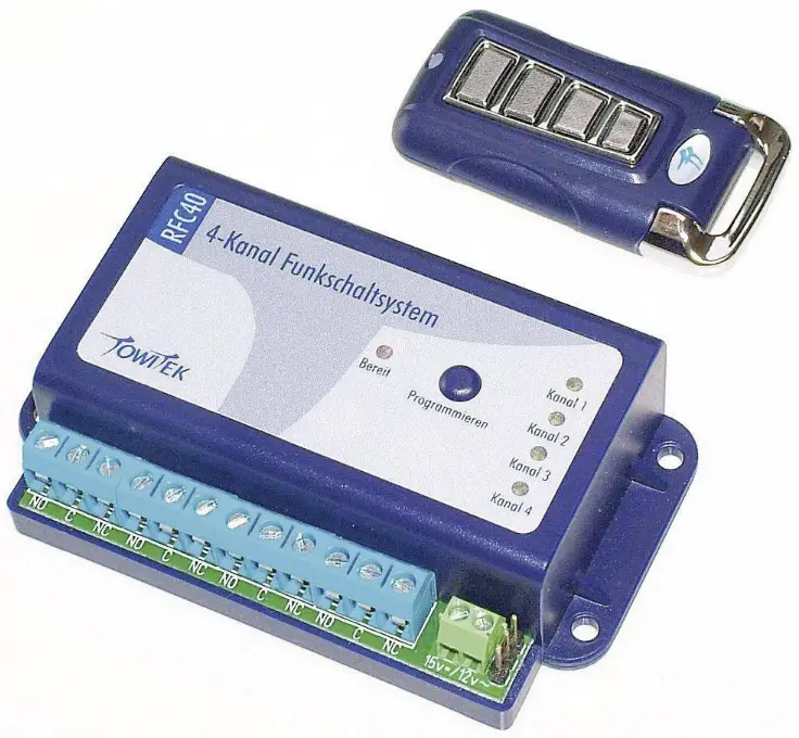
Features
Features of the 4-Ch receiver
- 4-Ch receiver with four separate relay outputs
- One handheld transmitter included with the set
- Each receiver could learn up to 50 transmitter keys
- Toggle or time mode can be individually configured for each of the four channels
- Built in antenna – range up to 50m with direct line of sight and no interference with other RF-noise
- Supply voltage 12-15V DC or 9-12V AC (@ 200 mA max.)
- Simple programming and configuration with single button
Features of the handheld transmitter
- Compact size dimensions of just 58 x 30 x 12 mm
- 4 buttons with tactile feedback
- Blue LED for showing transmitting activity
- Battery 12 V Type 27 A (included, already preinstalled)
- 48-bit security code
- Compliant with CE and RED requirements (433 MHz, <10 mW ERP) for use within EU countries
Up-to-date Operating Instructions
Download the latest operating instructions at
www.conrad.com/downloads or scan the QR
code shown. Follow the instructions on the website.
Explanation of symbols
The symbol with the lightning in the triangle is used if there is a risk to
your health, e.g. due to an electric shock.
The symbol with the exclamation mark in the triangle is used to indicate
important information in these operating instructions. Always read this
information carefully.
Safety instructions
Read the operating instructions carefully and especially observe the safety information. If you do not follow the safety instructions and information on proper handling in this manual, we assume no liability for any resulting personal injury or damage to property. Such cases will invalidate the\ warranty/ guarantee.
- The handling of products operating with electric current requires you to follow the rules from VDE such as VDE 0100, VDE0550/0551, VDE 0700, VDE 0711 and VDE 0860 or other local rules in your country.
- The product is not designed and authorized for use in life support or life saving applications! Do not use the product for applications in which a temporary or permanent failure or malfunction could cause damage to persons or property.
- If the module is used to switch voltages greater 24 V it is necessary to have the installation done with no voltage applied and performed by a trained professional authorized for such work. The module may only be used in such application if it was installed in a safe to touch enclosure.
- The module must only be used in dry and clean environment. The use near water, heavy dirt and/or high humidity is dangerous and not permitted.
- The product must not be used in conjunction with any type of flammable liquid or gas or other environment with risk of spark triggered explosions.
- Never exceed the limits or ratings listed in the “Technical Data” section at the end of this user guide.
- If the module is used in schools or educational facilities or similar institutions the operation must be supervised by trained and authorized staff.
- The product itself and all parts thereof (including packing material) are not suitable toys for children! (choking hazard, risk of electric shock, …)
Operation
The handheld transmitters will send a unique digital code for each of the 4 buttons pressed. Each receiver could learn up to 50 transmitter keys and associate them with one of the four relay channels. The assignment between buttons on the transmitter and channel on the receiver can be freely chosen. It is possible to use the same transmitter with several receivers.
- a) Learning new transmitter codes
With short pressing of the programming key on the receiver the ‘learning mode’ is entered: Programming key| LED| Function
---|---|---
Press short| Ch 1 LED blinking| Learning codes for Ch1
Press short again| Ch 2 LED blinking| Learning codes for Ch2
Press short again| Ch 3 LED blinking| Learning codes for Ch3
Press short again| Ch 4 LED blinking| Learning codes for Ch4
Press short again| LEDs off| Exit learning mode
In learning mode the receiver is waiting for codes received from transmitters. If no code is received for about 10 seconds, the receiver will exit learning mode and return to normal operation mode. If a code is received during learning mode, it is stored to memory and both LEDs will flash for confirmation
- b) Configuration of the two channels for toggle or timer mode
By keeping the programming button pressed for longer duration the configuration mode can be selected according to this procedure:
First step: choose channel****
| Press programming key and … | LED | Function |
|---|---|---|
| Release, after… | Ch 1 LED is lit | Setup mode for Ch1 |
| Release, after… | Ch 2 LED is lit | Setup mode for Ch2 |
| Release, after… | Ch 3 LED is lit | Setup mode for Ch3 |
| Release, after… | Ch 4 LED is lit | Setup mode for Ch4 |
Second step: choose desired mode
The mode of operation can be chosen individually for all channels. While the
LED of Ch1 – Ch4 is still lit from first step the programming key is pressed
again, and…
| Programming key | LED | Function |
|---|---|---|
| pressed again, and… | slow blink sequence | choosing mode |
| …release after 1st blink | toggle mode | |
| …release after 2nd blink | 0.5 sec. timer | |
| …release after 3rd blink | 5 sec. timer | |
| …release after 4th blink | 30 sec. timer | |
| …release after 5th blink | 1 min. timer | |
| …release after 6th blink | 5 min. timer | |
| …release after 7th blink | 15 min. timer | |
| …release after 8h blink | 30 min. timer | |
| …release after 9th blink | 1 hour timer |
-
c) Delete all transmitter codes from memory
For deleting all codes stored in the memory of the receiver the programming key is held down until all four LEDs are lit together (after 6- 7 seconds). The key is released and pressed again to confirm the deletion of the complete memory.
The completion of the memory formatting is confirmed with alternate blinking of both LEDs The setting of the toggle/timer mode for both channels is not affected by this procedure. -
d) Functions in normal operation mode
After learning codes from transmitters, all channels of the receiver can be controlled independent of each other according to the configured operation modes. The yellow LED for channels 1-4 indicate the current status of the associated relay. If the LED is lit, the terminals ‘NO’ and ‘C’ of this channel are connected electrically. If the LED is dark, the terminals ‘NC’ and ‘C’ of this channel are connected electrically
PLEASE DO NOT EXCEED THE MAXIMUM VOLTAGE OR CURRENT RATING FOR THE RELAY CONTACTS
Maximum range to be obtained:
The functional range is up to 50 meters under best conditions but could be
limited by objects blocking the line of sight between transmitter and
receiver. Other RF-noise on the same frequency (e.g. from babyphone, wireless
thermometer, or other 433 MHz devices) could also limit the effective range of
the remote set.
Changing the battery of the handheld transmitter
To replace the remote control battery (Type 27A, 12V, Alkaline), loosen the
two screws on the back of the transmitter housing and remove the back cover of
the housing. Observe polarity: The ‘+’ terminal of the battery must face the
flat contact plate. Used batteries must not be disposed of with the household
waste, but must be returned to a designated collection point.
External Antenna Connector
The 3-pin header on the right side of the terminal block for power supply is
for the connectionof an optional external receiver unit. If not using the
external receiver, please leave this connector open.
Mounting instructions
The 4-ch remote receiver could be mounted on almost any even surface, mounting
on metal may have a negative effect on functional range. Using the included
mounting clips, the case can be snapped onto DIN mounting rails with 30 mm
width.
Declaration of Conformity (DOC)
Conrad Electronic SE, Klaus-Conrad-Straße 1, D-92240 Hirschau hereby declares
that this product conforms to the 2014/53/EU directive. Click on the following
link to read the full text of the EU declaration of conformity:
www.conrad.com/downloads
Select a language by clicking on a flag symbol and enter the product order
number in the search box. You can then download the EU declaration of
conformity in PDF format.
Disposal
Electronic devices are recyclable waste and must not be disposed of in the
household waste. At the end of its service life, dispose of the product in
accordance with applicable regulatory guidelines. You thus fulfill your
statutory obligations and contribute to the protection of the environment.
Technical Data
- a) 4-Ch Receiver
- Dimensions …………………………….. 93 x 55 x 25 mm
- Input power …………………………….. 9 – 12 V/AC / 12 – 15 V/DC / max. 200 mA
- Contact rating ………………………….. Max. 250 V/AC / 30 V/DC / 5 A
- Allowed temp …………………………… 0 to +40 °C
- RF-frequency ………………………….. 433.92 MHz (433.05 – 434.79 MHz)
- b) 4-Ch Transmitter
- Features …………………………………. 4-buttons, activity LED
- Dimensions …………………………….. 30 x 58 x 12 mm
- RF-frequency ………………………….. 433.92 MHz (433.05 – 434.79 MHz)
- Transmission power …………………. < 10 mW ERP (as req. CE / RED )
- Transmission distance ………………. 50 m (line of sight)
- Battery ……………………………………. Type 27 A (12 V Alkaline)
References
Read User Manual Online (PDF format)
Read User Manual Online (PDF format) >>