Arnott MC-3585 Motorcycle Air Suspension System Instruction Manual
- October 30, 2023
- Arnott
Table of Contents
MC-3585 Motorcycle Air Suspension System
Instruction Manual
MC-3585 Motorcycle Air Suspension System
Congratulations on your purchase of an Arnott® Motorcycle Air Suspension
system. This system provides you with the ability to maintain your bike at a
constant level regardless of load, resulting in enhanced vehicle ride,
handling, and performance. We at Arnott Incorporated are proud to offer a high
quality product at the industry’s most competitive pricing. Thank you for your
confidence in us and our product. Proper installation is essential to
experience and appreciate the benefits of this system. Please take a moment to
review these installation instructions before you begin to install these
components on your motorcycle. The removal and installation of air suspension
products should only be performed by a fully qualified, ASE Certified,
professional.
It is equally important to be aware of all necessary safety measures while
installing your new Air Suspension System. This includes proper lifting and
immobilizing of the motorcycle and isolation of any stored energy to prevent
personal injury or property damage.
“Elevate Your Ride “ DOWNLOAD YOUR TÜV CERTIFICATE HERE:
ARNOTTCYCLES.EU/PAGES/TUV-CERTIFICATES
According to TÜV regulation, an air pressure gauge must be installed together
with the Arnott Motorcycle kit. Arnott recommends using their digital pressure
gauge K-3114 or K-3115 with motorcycle kits that have been certified for this
purpose
WARNING: DO NOT inflate the air suspension system until it is installed.
Inflation of the air suspension system before both ends are supported by the
motorcycle’s frame and/or appropriate suspension components may result in
serious personal injury and/or damage to the air suspension system. The
maximum recommended air spring inflation pressure is 200 psi. Arnott® is
committed to the quality of its products. If you have a question or problem
with any Arnott product, please contact Arnott by calling 800-251-8993 during
normal business hours or email
techassistance@arnottinc.com. (In the EU
please call +31 (0)73 7850 580 or email
info@arnotteurope.com)
BILL OF MATERIALS
MC-3585 – HARLEY-DAVIDSON SOFTAIL, BLACK
20-15878 – INFLATION KIT, HARLEY-DAVIDSON SOFTAIL CONTAINS:
PARTS LIST
QTY| PART NO.| DESCRIPTION
1| 21-3110| MICRO RELAY ASSEMBLY W/ HARNESS
1| 21-7715| 4MM VOSS FITTING ACCESSORY KIT
1| 21-7271| HARNESS CABLE TIES ACCESSORY KIT
1| 21-7272| SPLIT LOOM
1| 21-2698| UNIVERSAL FUSE HOLDER ASSEMBLY KIT
1| 21-12062| SOFTAIL COMPRESSOR ASSEMBLY
1| 20-12211| SOFTAIL MOUNT KIT
1| 11-MC-SOFTAIL3| MC-3585 & 3586 – INSTALL MANUAL
21-15824-B – SOFTAIL SHOCK KIT CONTAINS:
PARTS LIST
QTY| PART NO.| DESCRIPTION
1| 21-15820| SHOCK ASSY, BLACK
HANDLE BAR SWITCH KIT CONTAINS:
PARTS LIST
QTY| PART NO.| DESCRIPTION
1| 29-9749| HANDLE BAR SWITCH, BLACK
HANDLE BAR SWITCH KIT CONTAINS:
PARTS LIST
QTY| PART NO.| DESCRIPTION
1| 29-9750| HANDLE BAR SWITCH, CHROME
GENERAL INFORMATION:
Reading this manual signifies your agreement to the terms of the general release, waiver of liability, and hold harmless agreement, the full text of which is available at www.arnottcycles.com.
- Avoid damage to air lines and electrical components.
- Removal and installation is only to be performed by fully qualified personnel.
CAUTION: Damage to the motorcycle and air suspension system can be
incurred if work is carried out in a manner other than specified in the
instructions or in a different sequence.
Each owner or installer is unique, therefore installation of this system can
be done many different ways. The mounting locations of the compressor and
inflation switch are suggestions by our engineers. If proper wiring guidelines
and instructions are followed, relocation of the compressor or switch will
neither affect the system operation nor void your warranty. Adjust air shock
pressure as required for desired ride quality to maximize the benefits of your
system. Excess pressure will result in a firmer ride, too little pressure will
allow the suspension to bottom out.
To avoid the possibility of short circuits while working with electric
components consult your owner’s manual on how to disconnect your battery.
Refer to the Owner’s Manual for the bike and instructions for the motorcycle
lift for all correct lifting procedures. It is also recommended that you
protect any chrome or painted surfaces that may be damaged during lifting,
removal or installation process.
-
REMOVE REAR FENDER PANEL TO ACCESS SEAT MOUNT BOLTS. REMOVE THE SEAT MOUNT BOLTS. REMOVE THE SEAT. (FIGURES 1, 2, 3)


-
DISCONNECT AND CLEAR ANY WIRING HARNESS LEADS ATTACHED TO THE REAR SUB-FRAME AND FENDER. (FIGURE 4)

-
REMOVE LEFT AND RIGHT SIDE REAR FENDER PANELS (FIGURES 5, 6, 7, 8)


-
REMOVE REAR SUB-FRAME & FENDER. (FIGURES 9, 10, 11, 12)


-
PLACE AND RAISE A CENTER STAND MID-FRAME TO RELIEVE PRESSURE ON THE SHOCK. (FIGURE 13)

-
REMOVE THE ABS BRACKET. (FIGURES 14, 15)

-
UNROUTE THE PRE-LOAD ADJUSTER FOR REMOVAL. (FIGURES 16, 17, 18, 19, 20, 21)

-
LOOSEN PINCH BOLT AND REMOVE LOWER SHOCK BOLT. (FIGURES 22, 23)

-
REMOVE UPPER SHOCK BOLT AND REMOVE SHOCK. (FIGURES 24, 25)

-
LIFT REAR TIRE UNTIL SWINGARM IS BARLEY TOUCHING FRAME.
BUNDLE THE COMPRESSOR WIRES IN THE SPLIT LOOM TO PREPARE FOR INSTALL. (FIGURES 26, 27)
-
LOCATE THE EXISTING THREADED HOLES. APPLY BLUE LOCK TIGHT TO PROVIDED MOUNT BOLTS.
MOUNT THE COMPRESSOR ASSEMBLY TO THE THREADED HOLES. (FIGURES 28, 29, 30)
-
NOTE: WHEN MOUNTED ON MOTORCYCLE, AIR FILTER VENT MUST BE POINTING TOWARD THE GROUND. (FIGURE 31)

-
RUN BUNDLED SPLIT LOOM AND 4MM AIR LINE UP THE RIGHT SIDE OF FRAME. (FIGURE 32)
-
REMOVE THE LOWER CLUTCH PERCH BOLT. REUSING THE SCREW AND WASHER, ATTACH THE HANDLEBAR SWITCH TO THE PERCH WITH THE WASHER BETWEEN THE SWITCH MOUNT AND PERCH. ROUTE THE WIRES DOWN THE HANDLEBARS OR THE CLUTCH CABLE, UNDER THE FUEL TANK BACK TOWARDS THE BATTERY. FOLLOWING THE WIRING DIAGRAM IN THE BACK OF THIS MANUAL, COMPLETE THE ELECTRICAL CONNECTIONS. BUNDLE & TUCK ELECTRICAL COMPONENTS IN FRONT OF THE BATTERY. (FIGURES 33, 34, 35, 36)

-
SECURE WIRE LOOM TO WIRE HARNESS USING SUPPLIED ZIP TIES, RUN AIR HOSE TOWARDS UPPER SHOCK MOUNTING BOLT. TRIM THE AIR HOSE TO LENGTH. (FIGURE 37)
-
SCREW A VOSS FITTING INTO THE AIR SHOCK, FINGER TIGHT. THEN REMOVE THE WHITE PIN.
INSERT THE 4MM AIR HOSE INTO THE FITTING UNTIL YOU FEEL IT SEAT. REMOVE THE FITTING FROM THE SHOCK AND CONFIRM THE KEEPER IS ON THE HOSE. REINSERT THE FITTING INTO THE SHOCK AND SNUG TIGHT WITH A WRENCH. (FIGURES 38, 39, 40, 41)

-
INSTALL THE SHOCK IN THE MOTORCYCLE WITH THE AIR LINE FACING DOWN TOWARDS THE ENGINE (FIGURE 42)
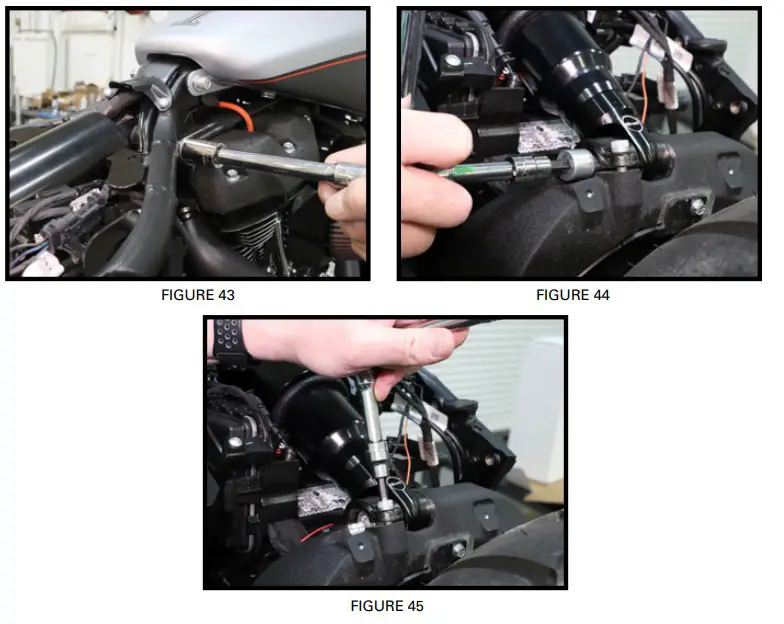
-
TIGHTEN THE UPPER AND LOWER SHOCK BOLTS. (FIGURES 43, 44, 45)
-
REINSTALL THE SEAT BRACKET, REAR SUB-FRAME/FENDER, AND SIDE PANELS (FIGURES 46, 47)

-
THE CLOCKING OF THE SHOCK EYES CAN BE CHANGED TO SUIT THE OWNER’S PREFERENCE . SIMPLY FIX THE LOWER EYE IN A VISE TO KEEP IT FROM MOVING. THEN GRASP THE DAMPER SLEEVE AS SHOWN BELOW. TWIST THE SLEEVE ON THE SHOCK BODY. (FIGURES 48, 49)

The terms Harley-Davidson®, Harley®, H-D®, Buell®, Softail®, Dyna®, V-Rod®,
Tri-Glide®, and Sportster® are used for reference only. Arnott Air Suspension
products are in no way authorized by nor associated with the Harley-Davidson
Motor Company. All references to Harley-Davidson terms and models are for
reference and identification purposes only. The use and installation of any
Arnott Air Suspension product or kit may adversely affect or void your Harley-
Davidson® factory warranty. It is the responsibility of the motorcycle owner
to check federal, state and local laws and ordinances before modifying or
customizing his or her motorcycle. It is the exclusive and total
responsibility of the motorcycle owner to determine the suitability of this
product for his or her use. The user shall assume all legal obligations,
personal injury risk and all liability duties and risk associated with the use
of this product. Arnott Air Suspension products are designed and intended for
the experienced on-road motorcyclists only and intended for closed course
operation. Arnott Air Suspension products and kits are designed exclusively
for OEM manufactured and equipped motorcycles with no modifications. Any
installation of aftermarket or customized components may adversely affect the
operation and performance of Arnott Air suspension kits and components and may
void the manufacturer’s warranty. These directions are accurate at time of
publication. Arnott Inc. reserves the right to revise specifications without
notice.
 AS SHOWN IN ILLUSTRATION
ABOVE;
AS SHOWN IN ILLUSTRATION
ABOVE;
- CUT SWITCH WIRING TO APPROPRIATE LENGTH.
- CRIMP THE TWO MALE SPADE CONNECTORS TO THE ORANGE WIRE AND TO THE BLACK WIRE.
- CRIMP THE FEMALE SPADE CONNECTOR TO THE DOUBLE RED WIRE.
References
Read User Manual Online (PDF format)
Read User Manual Online (PDF format) >>