nlt Digital Solutions AS14006 Lightning Bolt Instructions
- June 6, 2024
- nlt Digital Solutions
Table of Contents
nlt Digital Solutions AS14006 Lightning Bolt
Package Contents
- Lightning Bolt
- 2x Dual-band 2.4/5GHZ Omni Antenna 7/9dBi
Introduction
The N-Connex Lightning Bolt provides convenient WiFi capability to N-Connex- based networks. Built for harsh environments The Lighting Bolt is a compact 2.4/5GHz 2×2 MIMO wireless access point suitable for use some operations. The Lighting Bolt has two N-Type antenna connectors to fit an assortment of industry-standard antenna options. Powered by PoE, a single Cat6 cable provides network connectivity and power, making installation easy and intuitive. The secret power of the N-Connex Lighting Bolt is the built-in WiFi tracking function. When paired with NLTs flagship software Digital Mine and NLT WiFi tracking tags the N-Connex Lightning Bolt becomes a powerful tracking device. The Lightning Bolt is capable of tracking and reporting to NLT Digital Mine software, personnel, vehicles, or assets that are within its vicinity. The N-Connex Lightning Bolt can be deployed at a maximum distance of 300m from a PoE switch using Cat6 ethernet cables and N-Connex PoE extenders.
Features


Hardware Overview

Antenna
This radio transmitter [IC: 26833-AS14006] has been approved by Innovation, Science and Economic Development Canada to operate with the antenna types listed below, with the maximum permissible gain indicated. Antenna types not included in this list that have a gain greater than the maximum gain indicated for any type listed are strictly prohibited for use with this device.
Features

Antenna Pattern
Radiation Pattern Frequency 2.4GHz

Radiation Pattern Frequency 5GHz

Cable Connection
The NLT Lightning Bolt can be connected directly from a PoE Switch or a PoE Extender. The Bolt is a PoE Active device and needs a compatible power source. The maximum distance on a single run of Cat6 is 100m from the source. NLT recommend using cat6 AWG23 ethernet cable to minimize losses
Configuration
Connecting to Logging Page
The Lightning BOLT has a default IP address of 192.168.1.1 and a subnet mask
of 255.255.255.0
You must set your PC IP address to be on the same subnet as the Lighting BOLT
(that is, the PC and BOLT must both be on network 192.168.1.0/ 24). To access
the Lightning BOLT’s management GUI interface, follow these steps:
- Point the web browser to http://192.168.1.1
- Log into the interface by entering the default credentials
- Username: root
- Password: nltinc
- Click the “Login” button After successfully logging into the Lightning Bolt the GUI will change to the start page of the unit:
 The GUI is divided into two areas; the orange banner across the top of the screen that lists 5 menu items (the first 4 are menu groups) and the larger area below which displays relevant information and accepts all configuration changes made by the user. The page as presented after logging into the unit shows the information presented in Overview which is a submenu item under the Status menu. These menu items will be explained in the following sections.
Status
Overview
From the top menu navigate to Status Overview

- System: Shows Node Name, Model, Architecture, Firmware Version,Kernel Version, Local Time, Uptime, Load Average

- Memory: Shows Total Available, Free, Buffered

- Wireless: Shows a status summary of the different SSID configured on the AP note that it is possible to have multiple SSIDs programmed on the Bolt.

- Associated Stations: Shows brief information of devices currently attached to any of the SSIDs that are active on the Bolt.

System
System Properties
From the top menu navigate to System ->System
Local Time: This shows the local time. Sync with browser is done here
Hostname: Name of AP
Time zone: Select time zone from the list
Note: To apply any changes click Save & Apply at the bottom of the screen
Time Synchronization
From the top menu navigate to SystemSystem
Enable NTP Client: Tick to make the AP an NTP Client
Provide NTP Server: Tick make the AP the NT Server (Not Recommended)
NTP server Candidates: Input NTP IP. Multiple servers can be added
Note: To apply any change click Save & Apply at the bottom of the screen
Change Password
- From the top menu navigate to SystemAdministration
- Enter the new “Password”
- Re-enter the password “Confirmation”
- Click Save & Apply

Flash Operation
-
Backup / Restore
From the top menu navigate to SystemBackup / Flash Firmware
Download Backup-
Click Generate archive
-
The backup file (.gz) will download automatically Reset to defaults
-
Click Perform reset
-
The device will reboot, which may take a few minutes
Restore Backup -
Click Choose file
-
Find and select the file from your PC or Laptop (the file must be a tar file with the .gz extension)
-
Click open
-
Click Upload archive

Note : Do not power off the AP during this operation
Warning : Configurations are specific to a Firmware level and only in some cases they are back compatible. Ensure the backup is compatible with the Firmware of the AP. An unsupported configuration upload has the potential to corrupt the AP and lock it. For further information, please contact your NLT representative
-
-
Flash new firmware image
-
From the top menu navigate to System Backup / Flash Firmware.
-
Select Choose file.
-
Navigate to desired file on your laptop or PC and select it.
-
Select or unselect the “Keep settings” checkbox as required. If Keep settings is selected, the upgrade to the new firmware will retain all configuration settings that had been set previously. If unchecked, the Lightning Bolt will return to a factory default state (including IP address and password). Only tick “Keep settings” if the new firmware is compatible with the existing configuration. If unsure do not select this check box or contact your NLT representative for advice.
-
Click Flash Image

-
Ensure that there is no error message in the Flash Firmware -Verify page.
-
Click Proceed
Note : The FW upload/reflash can take some time, do not disconnect, or turn off the bolt during this process.
Warning : configurations are specific to firmware version and only in some cases they are backwards compatible. Changing firmware without ensuring the current configuration is compatible with the desired firmware has the potential to corrupt the AP and lock it. For further information, please contact your NLT representative
Reboot
- From the top menu navigate to System Reboot
- Click Perform reboot
Tracking
- From the top menu navigate to Services Wifitrackd
- Tick/Untick Tracking Enable/Disable to turn on and Off Tracking

- Navigate to Minimum Signal to be Reported and change value to desired value

- Click Save and Apply
Warning : Wrong configuration of thresholds could result on errors on the tracking logic. For further information, please contact your NLT representative
Network
VLANs
From the top menu navigate to Network VLANs This page allows for different VLANS to be assigned to the corresponding SSID’s. From this menu you can Add, Delete or Edit VLANs
Management VLAN
- From the top menu navigate to Network VLANs
- Input the new VLAN ID for the management of the AP
- Tick Enable
- Input a VLAN name. (Default: NLT_Digital)
- Set the VLAN Priority (It is recommended to leave it as 2)
- Click Save & Apply

Warning : Do not select enable if the management of the AP is on (VLAN 1). Incorrect configuration can potentially lock the device.
VLANs Configuration
- From the top menu navigate to NetworkVLANs
- Click Add
- Select the new VLAN ID (accepted range is 1-4094)
- Tick Enable
- Input a VLAN name. (It is recommended to name the VLAN the same as the VLAN ID)
- Set the VLAN Priority accordingly 7(Highest), 0 (Lowest)
- Click Save & Apply
Note : Do not power off the AP during this operation
Wireless
From the top menu navigate to Network Wifi Within this menu you can add, edit
remove or disable SSIDs on the 2.4GHz and 5GHz band.

Add button: Create a new SSID on either the 2.4GHz or the 5GHz band.
Remove button : Delete a specific SSID configuration on either the 2.4GHz
or the 5GHz band.
Edit button : settings of an existing SSID on either the 2.4GHz or the
5GHz band.
Wireless 2.4GHz (802.11bgn)
On the wireless overview, navigate to the 2.4GHZ section and click Edit on the
SSID to action

There are two sections: Device Configuration and Interface Configuration The Device configuration area allows the user to setup the settings associated with the RF performance of the device. There are two tabs in this area: General Setup and Advanced settings. The Interface Configuration area, which has three tabs: General Setup, Wireless Security and Advance Settings. This area, particularly General Setup and Wireless Security allows the user to configure or modify the specific settings of the SSID. The following descriptions give details of each of the relevant settings and information.
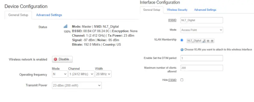
Device Configuration
General Setup Tab
The wireless network is enabled: Disable/Enable the Wireless network by
clicking the button
Operating Frequency Buttons:
- (Mode) the dropbox selection shows the WiFi mode that will be used for this SSID. The choice is Legacy (802.11b and g) or N (802.11n)
- (Channel) the dropbox selection shows the available channels for selection, this depends on the country selected.
- (Width) the dropbox selection shows two bandwidths for selection
Note : To apply changes click Save & Apply or for many changes click Save and after finishing click save & Apply (at the bottom of the screen)
Advanced Settings Tab
Select the advanced settings tab Country Code: The dropbox selection shows the
available country codes (ISO/IEC Alpha2). This Selection affect the Operating
Frequency and the Transmit power
Note : To apply changes click Save & Apply or for many changes click Save and after finishing click save & Apply (at the bottom of the screen)
Interface Configuration
General setup Tab
ESSID : Input SSID name
Mode : The drop box selection shows the available Modes the NLT Bolt Operates. See image below.
Note : Configuration of most the common application, Access Point will be used in following section. For advanced configuration contact your NLT representative.
VLAN Membership : Select from the list of pre-created VLANs. This associates the SSID to a corresponding VLAN
Enable Set the DTIM Period : The period to wake up wireless clients from Sleep Mode. For voice application it is recommended to be set to 1
Maximum number of Stations allowed: Limits the amount of active connections to the access point, set to 255 by default.
Hide ESSID : Tick to hide/show SSID. Most applications will show the SSID but hiding it may add a layer of security.

Note : To apply changes click Save & Apply or for many changes click Save and after finishing all the changes click save & Apply (at the bottom of the screen)
Wireless Security Tab
Encryption: The drop box selection shows the available type of encryptions
available. See image below:
Note : For This section WP2-PSK is used. Cipher: Subtype of encryption
Key : Enter the pre-shared Passkey to be used by devices that will associate with this SSID. Note that the key must meet the criteria of the Security setting chosen.

Note: To apply changes click Save & Apply or for many changes click Save and after finishing all the changes click save & Apply (at the bottom of the screen)
Advance Setting Tab
802.11h : This minimizes data loss when radio moves to the new channel
Separate Clients: The drop box selection shows the available type of encryptions available.
UAPSD Enable: Tick to enable. This feature reduces the latency of traffic flow that is delivered over the wireless media.
Multicast Rate: The multicast rate is the minimum speed that a wireless device must be able to communicate at in order to connect to the router. So, the lower the multicast rate, the further away, or more accurately, the weaker the wireless signal, are allowed to connect
Fragmentation Threshold: This value is used to set the maximum size of a packet that can be sent. Smaller packets improve reliability, but they will decrease performance. Common Value 1584
RTS/CTS Threshold: Typical threshold is 1609
WMM Mode: Tick to enable Wi-FI Multimedia. QoS features (Voice, Video, etc)
On the wireless overview, navigate to the 5 GHZ section and click Edit on the SSID to action

There are also two sections on the 5GHz configuration: Device Configuration and Interface Configuration The following descriptions give details of each of the relevant settings and information.

Device Configuration
General Setup Tab
Wireless network is enabled: Disable/Enable the Wireless network by clicking
the button
Operating Frequency Buttons:
(Mode) the drop box selection shows the WiFi mode that will be used for this
SSID. The choice is Legacy (802.11a ), N (802.11n) or AC (802.11AC) (Channel)
the drop box selection shows the available channels for selection, this
depends on the country selected. (Width) the drop box selection shows two
bandwidths for selection 20MHz, 40MHz and 80MHz
Note: To apply changes click Save & Apply or for many changes click Save and after finishing click save & Apply (at the bottom of the screen)
Advance Settings Tab
Select the advanced settings tab
Country Code : The drop box selection shows the available country codes
(ISO/IEC Alpha2). This Selection affect the Operating Frequency and the
Transmit power
Note: To apply changes click Save & Apply or for many changes click Save and after finishing click save & Apply (at the bottom of the screen)
Interface Configuration
General Setup and Wireless Security Tab are Configure identically than the
2.4GHZ wireless (refer to page 18)
Advance Setting Tab
The configuration is done identical to the 2.4GHvz except for: Number of
Spatial Streams: Parameters MIMO. System 2×2 LDPC: Low-density parity-check
(LDPC) code is a linear error correcting code, a method of transmitting a
message over a noisy transmission channel RX STBC: Space -Time Block Coding Rx
TX STBC: Space -Time Block Coding Tx
Network Administration – Change IP Address The factory default IP address of the Bolt is 192.168.1.1 /24. It should be changed to an address that is compatible with the network’s IP schema. The following instructions provide details to do this:
- From the top menu navigate to Network Lan Interface

- Click Edit
- Modify the IP address and other relevant details
- Protocol: Chose between Static or DHCP (Static Recommended)
- IPv4 address: Enter the IP address to be used for the Bolt
- IPv4 netmask: Enter the network mask that is relevant for the network
- IPv4 gateway: Gateway (Important for routing)
- IPv4 broadcast: Auto-generated (no entry required)
- Use custom DNS servers: At this time, this entry can be left blank
Warning: Entering the wrong information (ie incorrect IP address) can make the device inaccessible. Double check your entries in these fields.
Contacting Technical Support
Contact your local NLT Digital representative or visit us www.nltdigital.com
FCC Statement
Any Changes or modifications not expressly approved by the party responsible
for compliance could void the user’s authority to operate the equipment. This
device complies with part 15 of the FCC Rules. Operation is subject to the
following two conditions:(1) This device may not cause harmful interference,
and (2) This device must accept any interference received, including
interference that may cause undesired operation. FCC Radiation Exposure
Statement:
This equipment complies with FCC radiation exposure limits set forth for an
uncontrolled environment .This equipment should be installed and operated with
minimum distance 20cm between the radiator& your body.
ISED RSS Warning:
This device complies with Innovation, Science and Economic Development Canada
licence-exempt RSS standard(s). Operation is subject to the following two
conditions: (1) this device may not cause interference, and (2) this device
must accept any interference, including interference that may cause undesired
operation of the device.
ISED RF exposure statement:
This equipment complies with ISED radiation exposure limits set forth for an
uncontrolled environment. This equipment should be installed and operated with
minimum distance 20cm between the radiator& your body.This transmitter must
not be co-located or operating in conjunction with any other antenna or
transmitter.
Note : This equipment has been tested and found to comply with the limits
for a Class B digital device, pursuant to part 15 of the FCC Rules. These
limits are designed to provide reasonable protection against harmful
interference in a residential installation. This equipment generates,uses and
can radiate radio frequency energy and, if not installed and used in
accordance with the instructions, may cause harmful interference to radio
communications. However, there is no guarantee that interference will not
occur in a particular installation. If this equipment does cause harmful
interference to radio or television reception, which can be determined by
turning the equipment off and on, the user is encouraged to try to correct the
interference by one or more of the following measures:
- Reorient or relocate the receiving antenna.
- Increase the separation between the equipment and receiver.
- Connect the equipment into an outlet on a circuit different from that to which the receiver is connected.
- Consult the dealer or an experienced radio/TV technician for help.
Read User Manual Online (PDF format)
Read User Manual Online (PDF format) >>