OCULii 2AXVNFALCON Vehicular Radar Systems User Manual
- June 5, 2024
- OCULii
Table of Contents

OCULII - FALCON
USER MANUAL

EDITION 0.3.3
October 2020
Oculii Corporation
Copyright © 2020. All rights reserved
829 Space Drive, Beavercreek, Oh 45434, USA
Phone: 937-829-0383
Email: info@oculii.com
Website: www.oculii.com
1. FCC MANUAL STATEMENTS
FCC ID: 2AXVNFALCON
Grantee Code: 2AXVN
Model: FALCON
This device complies with Part 15 of FCC Rules. Operation is subject to the following two conditions: (1) this device may not cause harmful interference, and (2) this device must accept any interference received, including interference that may cause undesired operation.
Changes or modifications not expressly approved by OCULII LLC could void the user’s authority to operate the equipment.
This transmitter must not be co-located or operating in conjunction with any other antenna or transmitter.
FCC RF Radiation Exposure Statement
This equipment should be installed and operated with a minimum distance of 20cm between the radiator and your body.
This transmitter complies with FCC radiation exposure limits set forth for an uncontrolled environment.
2.1 PRODUCT OVERVIEW
Oculii’s Falcon radar is intended for automotive use and operates in the 76-81GHz band. These radars are integrated into a vehicle to improve vehicle safety systems. They can be integrated to a vehicle as stand along sensors, a set of sensors or a part of more complex systems that can include cameras, lidars, and other types of sensors. The aim is to use these stand along or integrated systems to provide features such as Automatic Cruise Control (ACC), Automatic Emergency Braking (AEB), Blind Spot Detection and Level 1-5 autonomous driving.
Powered by Virtual Aperture Imaging, Oculii’s FALCON Point Cloud Radars can deliver thousands of points per second, capturing all relevant environmental information. Oculii’s radar point clouds perform in all weather conditions, and each point directly measures highly accurate doppler information, enabling immediate separation and efficient tracking of any moving targets.
Virtual Aperture Imaging (VAI) is an array multiplier technique that can be used on any transceiver architecture. The Oculii FALCON is a single chip, automotive grade sensor. Using VAI, Oculii’s FALCON can achieve ~1-degree angular resolution across a wide Field of View.
2.2 PRODUCT APPLICATION EXAMPLES
– Automatic Cruise Control (ACC)
– Automatic Emergency Breaking (AEB)
– Blind Spot Detection
– Collision Prevention Systems
– Automatic Lane Change Systems
– Level 1-5 autonomous driving applications.
– Simultaneous Localization and Mapping (SLAM).
– Intelligent Transportation Systems (ITS).
– Etc.
3.RADAR TECHNICAL SPECIFICATIONS
| Frequency Band | 76.0 – 81.0GHz |
|---|---|
| Cycle Time | 100ms |
| Data Output Format | CAN-FD |
| Modulation | TDM FMCW |
| Weight | 138g |
| Dimensions (WxHxD) | 126.95 x 84.50 x 17.00 mm |
| Power Consumption | 2.4 W |
| Input Operating Voltage | 12V (+8V to +24V input) |
| Operation Temperature | -40 to +105 C |
| Vehicle Physical Interface | Molex 10 pin 349671001 |
| Range | 25m – 300m |
| Field of View | 120 degrees |
4. HARDWARE DESCRIPTION AND MOUNTING INFORMATION
The radar assembly consists of a single PCB containing all the RF components antennas, analog to digital converters, and all the necessary components for signal communication with the vehicle and power.
Dimensions

All dimensions are in mm
Mounting

All dimensions are in mm

All dimensions are in mm
Not to scale
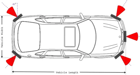
Multiple Sensor Mounting on a Vehicle
5. CONNECTION
Components:
a) Falcon Sensor
b) Wiring Harness
c) Power Source - 12V, 0.5/1.0A
d) CAN to USB Converter

Connection Instructions
– Connect the Wiring harness to the Falcon sensor.
– Connect the power source to the wiring harness.
– Connect the CAN to USB converter to the wiring harness.
– Connect the USB to a PC to read/visualize data.
Block Diagram

- CAN to USB converter
- DB9 RS232 Breakout board
- Molex Connector (349671001)
- Stripped Wire
- 12 V Power Supply
- Pigtail female plug
The Can_High, Can_low & Can_Gnd are differential signals and it should
be twisted among themselves only.
These wires should not be twisted with other wires. This way we reduce
interference between signals.
Pinout
Falcon Pinout
6. REVISION HISTORY
| Revision | Date | Author | Description |
|---|---|---|---|
| 0.3.1 | 08.06.20 | Mihiraan Singh | Initial Draft. |
| 0.3.2 | 10.05.20 | Mihiraan Singh | Section 1 edited. |
| 0.3.3 | 10.19.20 | Mihiraan Singh | Grantee Code updated. |
Read User Manual Online (PDF format)
Read User Manual Online (PDF format) >>