NeoR TG MINI Heat Pump Air Water Instruction Manual
- June 13, 2024
- NeoR
Table of Contents
Installation manual
NeoRé TG MINI
Heat pump air-water
NeoRé 5TG MINI
NeoRé 8TG MINI
NeoRé 11TG MINI
NeoRé 14TG MINI
NeoRé 8TG MINI HP
NeoRé 11TG MINI HP
NeoRé 14TG MINI HP
NeoRé 16TG MINI HP
All rights and changes reserved. Last update
Introduction
Installation manual extends User manual by more informations. This manual is
designed primarily for construction companies and heating engineers, which
realise installation of outdoor and indoor unit of NeoRé heat pump and connect
it to the heating system.
Second part of this manual is designed for service organisations and
engineers. In this part is an explanation of error codes and instructions for
device maintenance.
Safety instructions
2.1 Safety warning
Read the manual carefully before installing, putting into operation or
maintaining the device. Adherence to the described procedures for the
installation and operation of the device is important for long-term and
trouble-free operation. Faults and defects caused by non-compliance with the
safety instructions, installation procedures and operating rules will not be
taken into account, not even damage or destruction of other related equipment.
The device may only be installed by persons with appropriate qualifications in
the field of heating, cooling and electrical engineering.
In addition, observe all applicable safety regulations related to the actual
installation and operation of the NeoRé heat pump.
The device may only be operated by a person familiar with this manual and
older than 15 years. Persons with limited physical, sensory and mental
capabilities or with lack of experience and/or knowledge may operate the
device only if they are supervised or trained in the safe use of the device by
the person responsible for their safety and if they understand the dangers
involved. Children must not play with the device or clean or maintain it.
The R32 refrigerant is a class A2L flammable gas.
To install the indoor unit, observe the minimum floor area requirement. More
in InstallationManual, Table Minimum floor area when using A2L gas in Chapter
Refrigerant piping.
The heat pump must be installed in a room without continuous open ame operation (e.g. running gas appliance) and ignition sources (e.g. operating electric heater).
2.2Safety precautions
The heat pump is an electric device working with a voltage of 400 V! The
device may only be installed and serviced by an authorized electrician. In
case of fire, do not extinguish with water or foam. Use only a powder or snow
extinguisher!
In the event of a refrigerant leak, turn off all circuit breakers located on
the indoor unit and contact the service organization indicated on the plate on
the indoor unit. The R32 refrigerant is slightly flammable, non-toxic. Under
no circumstances should you try to stop the refrigerant leak yourself. It
reaches very low temperatures (up to —50°C). In the event of a leak in the
interior of a building, ventilate the room. In case of inhalation of
refrigerant vapours or fire fumes, take the affected person to a ventilated
place and call for medical help: phone number 112.
In case of contact with liquid refrigerant, dry the area immediately and warm
it, for example with a blanket. In case of contact with eyes, rinse
immediately with plenty of lukewarm water and call for medical help: phone
number 112.
In case of fire, disconnect the device from the mains and extinguish with a
snow or powder fire extinguisher.
In the event of a heating water leak, turn off all circuit breakers located on
the indoor unit and contact your service organization.
When handling the refrigerant piping (cleaning, maintenance), use personal
protective equipment (gloves, goggles, protective clothing, …).
Do not put your hands or other objects in the fan area of the outdoor unit,
there is a risk of serious injury!.
Do not expose yourself to the airflow from the outdoor unit for a long time.
There is a risk of severe hypothermia!
- Perform the installation only in accordance with the installation manual, which is available at l https://www.neota.cz/en/downloads/.
- Connect the outdoor and indoor unit (refrigerant, electric) only with the material specified in the installation manual.
- Installation work on the refrigerant and electric circuit must be performed by an appropriately authorized person.
- Do not use flexible inlets and piping to connect the units.
- Do not operate a device that is not completely installed.
- Do not use refrigerants whose quality and purity you are not sure about. Observe the safety precautions on the refrigerant packaging.
- Do not add refrigerant to increase performance.
- Always use a vacuum pump before filling the refrigerant.
- Pay attention to work safety and personal protective equipment during installation.
- The device must be installed by a specialist company authorized by the manufacturer. Do not attempt to install the device yourself. You can destroy the device or cause injury.
- Do not mix two types of refrigerant. Use only the refrigerant specified on the label.
2.3 Legal conditions
Legal conditions that must be observed when handling the device.
CSN EN 378-4+A1:2020 Art. 6.5.x
All parts of refrigeration equipment, e.g. refrigerant, oil, heat-transfer
medium, filter, dehydrator, insulating material, compressor and the entire
refrigerant circuit equipment must be recovered, reused and/or properly
disposed of in connection with maintenance, repair and decommissioning.
Maintenance and disposal must be performed by a person professionally
qualified for the disposal of refrigerants and oils.
CSN EN 378-4+A1:2020 Art. 6.2.x
Used refrigerant that is not intended for reuse must be treated as waste for
safe disposal. Prevent emissions to the environment. Any handling of the
refrigerant must be performed by a person professionally qualified for the
disposal of refrigerants and oils.
CSN EN 378-4+A1:2020 Art. 6.2.x
Used oil recovered from refrigeration equipment that cannot be regenerated
must be stored in a suitable separate container and must be treated as waste
for safe disposal. Oil must be drained by a qualified person.
CSN EN 378-4+A1:2020 Art. 6.6
All activities related to recovery, reuse of refrigerant and refrigerant
source must be recorded in the refrigeration equipment’s operating log (see En
378-4 Art. 4.2). If required, it must be provided by the refrigerant supplier
or service company.
2.4 Storage and transport conditions
Indoor unit NeoRe IUM 16-20 or IUM 18-16
Environment dust-free, non-aggressive
Temperature range -10 to 45°C
Relative humidity max 70%
Outdoor unit OU GMx or OU GPx
Environment dust-free, non-aggressive
Temperature range -10 to 45°C
Relative humidity max 90%
The outdoor unit must be stored and transported in a vertical position in the
original packaging and properly se- cured. If necessary, protect fragile
parts, especially the evaporator, from damage. Overturning or leaking
refrigerant may lead to injury.
During transport, all components of the device must be secured with straps or
other technical means to prevent over- turning and injury.
lf damage or refrigerant leakage occur during transport, do not attempt to
stop the leak improperly. Evaporation of the refrigerant significantly cools
the affected areas and may cause injury in contact with the skin.
2.1 Table of technical parameters

Installation manual
The heat pump may only be installed in accordance with the safety
instructions, see chapter|2 Safety instructions (p. 5).
3.1 Working conditions
The heat pump can be used as a heat source for
- heating
- water heating (additional equipment required – DHW heating set)
- cooling
Freezing of the coolant exchanger – The basic protection against freezing of
the coolant/water exchanger is to ensure minimum flow through the exchanger,
see project documentation. Such accident of the coolant exchanger can only
occur during defrosting the evaporator, or cooling. It is necessary to ensure
that no control element is inserted in the heating circuit, that could close
or significantly reduce the heating water circulation. When starting the heat
pump for the first time and after a shutdown, ensure that the water in the
heating circuit has at least 20° C.
According to CSN 33 2000-3, the heat pump must not be located and installed in
an environment with a risk of explosion of flammable gases.
3.1.1 Working environment
environment according to CSN 33 2000-3 for an outdoor unit AA2; AA3; AA4; AAS;
AB7; AD3
environment according to CSN 33 2000-3 for an indoor unit AA5; AB5
Technical parameters of el. connections
nominal voltage| x/V; +/-%; Hz
maximum power| according to table of technical parameters
grid type| TN-CS according to ČSN EN –
ingress protection| I according to ČSN EN 6-
outdoor unit ingress protection| IPX
indoor unit ingress protection| IP/ (with / without cover)
Table 3.1: Technical parameters of el. connections
3.1.2 Cooling circuit
refrigerant R32, CH2F2, GWP 675, refill by type (table of technical parameters
on page|8)
maximum overpressure 4.2 MPa
The working range of output water temperature can be found in the
figure|8.3|on page 48.
3.1.3 Technical parameters of heating / cooling water
Before the installation we recommend to make water analysis. Each material
reacts when come to touch with water. Type of reaction depends on substances
containde in water. Water with higher content of salt, calcium and magnesium
sedimenst in form of limescale after warming up to 60°C. It is an irreversible
procedure which causes significant deterionation of whole device and
significant decrease of efficiency.
Generally recommended operating water parameters:
- pH 6,5-8,5
- conductivity under 350 us/cm
- hardness 2-6°dH
- bacteria NE
- mechanical impurities NO
3.1.4 Technical parameters of water
Inlet water quality for stainless steel tank must not exceed following parameters:
- Calcium (Ca) + Magnesium (Mg) = 1,25 mmol/I
- Ferrum (Fe) = 0,2 mg/I
- Mangan (Mn) = 0,05 mg/|
- Chloride (Cl) = 0,03 mg/|
- Chlorides = 100 mg/|
- Water hadrness less than or equal to 7°dH
lf the inside of water tank will be damaged in cause of exceeding the
parameters of water, there is no claiming warranty from the manufacturer.
lf the water does not meet parameters, it is needed to connect a mechanical
filter to cold water inlet and install convient water threatment.
More in chapter|7.3 Hot water tank maintenance (p. /41)
Overpressure and temperature
highest overpressure| , bar
highest working overpressure| ,8 bar
highest working temperature| 60°C
Table 3.2: Overpressure and temperature
The minimum heating water flow rate for each power type is shown in the figure
|8.2)on page|47|
3.2 Preparation of space for the outdoor unit
When choosing an area for the outdoor unit, it is necessary to consider
current legislation and choose the location so that the day-time or night-time
noise limits on the site boundaries are not exceeded. Ambient materials (wall,
bushes, solid area, green area, etc.) significantly affect propagation of
noise. Therefore, it is advisable to draw up a noise study prior to physical
location of the outdoor unit.
When choosing an area for the outdoor unit, it is necessary to keep the
minimum distances from the surrounding objects for the sake of air flow
through the device. Failure to observe these distances may have a major impact
on the correct functioning and performance of the device.
It is also necessary to secure the unit against tipping and ensure condensate
drainage from the unit so that no ice freezes are formed under it in the
winter months. The condensate drainage method depends mainly on the climatic
conditions in which the unit is installed. Heating cable under unit is
recomended in cold climate, to melt an ice and help the water soak up. The
space around the unit must be maintained clear of snow and other things.
Minimum spacing distances

Figure 3.1: Drawing of foundation for the outdoor unit – floor plan
1 – wall; 2 – passage through the wall into the interior; 3 – drainage pit;
4 – concrete masonry; 5 – drainage hose
Dimensions dependent by outdoor unit type
Outdoor unit| dimension A
NeoRé , 8, , TGx, NeoRé 6 TGx HP| 6 mm
NeoRé 8, , TGx HP| 6 mm
Table 3.3: Console pitch depending on outdoor unit type (x = TX, MINI or MINI+)
lf a universal console for NeoRé is used, the base width is 620 mm, see
separate instructions.
Images [3.1 and|3.2|(p. (13) show the way space can be prepared for
installation of the outdoor unit. The image [8.1 indi- cates minimum distances
from the walls. This is the worst acceptable scenario that still enables
proper functioning of the device. There must be no fixed obstacle in front of
the unit, at least one meter away. Always ask supplier for the correct install
method for your system.
The dimensions of the drainage pit are, again, marked with regard to good
functionality and convenient implementation.
Inside the drainage pit, there are masonry blocks filled with concrete. During
casting, it is advisable to insert threaded rods that will anchor the console
under the outdoor unit, into the concrete pillars. Another option is to anchor
the threaded rods with chemical mortar.
 At the
bottom of the drainage pit, especially if the soil is clayey and impermeable,
it is recommended to insert a drainage hose, which must be at least 800 mm
outside the drainage pit, covered in geotextile and stored in pebbles.
Likewise, the entire area of the drainage pit will be filled with pebbles to
ensure proper water drainage and allow it to soak into the subsoil.
At the
bottom of the drainage pit, especially if the soil is clayey and impermeable,
it is recommended to insert a drainage hose, which must be at least 800 mm
outside the drainage pit, covered in geotextile and stored in pebbles.
Likewise, the entire area of the drainage pit will be filled with pebbles to
ensure proper water drainage and allow it to soak into the subsoil.
To fit the outdoor unit, use a console to ensure that the unit is higher than
the surrounding terrain. This results in a lower rate of clogging of the
exchanger with surrounding dirt from the ground and, above all, the passage of
air through the snow in winter is not limited. Before fitting the outdoor
unit, the console must be mounted.
The passage through the wall needs to be higher than the outlets from the
outdoor unit, so that during rain, water will run off the object.
3.3 Fitting the outdoor unit
Before fitting the outdoor unit, it is necessary to check whether the console,
on which the unit is to be mounted, is well anchored. Under no circumstances
should the outdoor unit be fitted unless the console is securely anchored.
The outdoor unit must be fitted with a minimum of two workers. Once seated on
the console, one of the workers holds the unit in a stable position while the
other one secures the unit with screws at the bottom. The entire concrete
foundation assembly, including the console and the outdoor unit, is shown in
the picture |3.2/(p. (13).
The unit must be attached to the bottom console with M6x70 mm screws and these
must be tightened properly.
3.4 Preparation of space for the indoor unit
The indoor unit is designed for wall mounting. Upon installation, you need to
keep the minimum wall and ceiling distances that are shown in the picture|3.1
p. [12| There is an allocated space under the unit itself that should be kept
free for the connection of the heating circuit, refrigerant piping and cable
connections.
It is also necessary to take into account the weight of the device and choose
the appropriate wall and anchoring tech- nology with respect to it.
3.5 Indoor unit mounting
After selecting the appropriate space to place the indoor unit, first step is
to fix a mount pad on the wall. There are holes in the pad that anchor it to
the wall by fixing with screws. Recommended screws are min. 5×70.
When anchoring, keep in mind that the mounting pad will have to bear the
weight of the entire indoor unit. Therefore, it is necessary to use an
anchoring system with sufficient load-bearing capacity and suitable for
material of the relevant wall.
The mounting pad is shown in the picture|3.4/(p. [16) After fixing the
mounting pad, it is possible to hang the indoor unit.
Due to the size and weight of the unit, at least two workers are required to
hang it on the pad. The indoor unit hangs on hooks that are located directly
in the back of the unit. After hanging the unit, it is necessary to secure the
it against unwanted falling with two screws at marked places at the bottom.
Handling, hanging and mounting the indoor unit requires at least two workers
and the use of personal protective equipment.
3.6 Units connection
Several connections must be made between the indoor and the outdoor units
without which the heat pump as a whole will not be able to operate.
It is necessary to prepare the piping for the refrigerant circuit where the
heating medium is transferred. Then it is necessary to prepare the power
supply cable for the indoor unit, the power supply cable for the outdoor unit,
the indoor / outdoor communication cable, the outdoor temperature sensor cable
and optionally the indoor temperature sensor. The location of the temperature
sensors must be consulted with a specialist as their improper location can
have a major impact on the quality of the heat pump operation.

3.6.1 Refrigerant piping
It is very important to prevent any dirt and moisture from getting into the
pipes of the refrigerant piping. Dirt or moisture could cause damage or even
complete destruction of the entire device.
It is also advisable that the pipeline outside the building is as short as
possible and well insulated to minimize the losses. If the pipeline is buried
underground, moisture insulation, in addition to thermal insulation, is
required.
The indoor and outdoor units must be interconnected by a pair of pipes, one of which serves for leading liquid refrigerant and the other for refrigerant in gaseous state. It is necessary to use a thick-wall copper tubes for refrigeration with a polished inner wall. For gaseous refrigerant, a 3/8 inch diameter and 1mm wall thickness is intended. A 3/8 inch diameter and 1 mm wall thickness tube is intended for liquid refrigerant. Greater wall thickness is used for increased durability and longer service life. Nevertheless, care must be taken when handling and shaping the pipes to avoid sharp bends and breaks. Use a cutting wheel to divide the pipes.
| Type | Liquid refrigerant | Refrigerant gas |
|---|---|---|
| NeoRé TG | /” (6, mm) | /” (, mm) |
| NeoRé 8,,,6TG (HP) | /8″ (, mm) | /8″ (,88 mm) |
Table .: Refrigerant pipe diameter, wall thickness mm
R32 refrigerant is an A2L class flammable gas.
R32 refrigerant is very low flammable and difficult to ignite. The burning
rate is 6.32 cm/s.
A spark generated by the electrical switching elements or the lighting switch,
for example, do not have sufficient energy to ignite the R32-air mixture.
The minimum floor area condition must be met to install the indoor unit.
According to EN 378, the minimum floor area for residential installations is
determined while using A2L gas, see table. If the minimum floor area condition
is not met, it is necessary to ventilate the room.
In the case of room ventilation, the ventilation openings must be unobstructed
| Type | Minimum oor area |
|---|---|
| NeoRé TG | , m2 |
| NeoRé 8 TG HP | , m2 |
| NeoRé ,,6 TG HP | , m2 |
Table 3.5: Minimum floor area when using A2L gas
To work with R32 refrigerant, the installer must have a valid Ministry of
Environment certificate according to EU regulation 2015/2067. It is also
necessary to use special tools (vacuum pump, aspirator) approved for use with
R32. Avoid mixing oxygen with R32. Always use nitrogen to test for leaks of
pipeline.
The refrigerant should be handled with care, and protective equipment to
protect skin, face and eyes from possible frost damage should be worn.
In case of capping, do not use any mineral oils. Mineral oils can reduce the
service life of the equipment.
lf the pipes are connected by soldering, a hard solder must be used (min. 30%
Ag) and the piping must be filled with nitrogen to prevent scale formation.
The gas must not be pressurized.
Use insulation suitable for refrigerant circuits. Pipe surface temperature can
reach up to 120°C! For outdoor use, use insulation at least 20 mm thick. For
interior spaces, 10-15 mm is sufficient. These parameters apply to insulation
that meets a thermal resistance of 0.045W / (mK) or better (at 20°C)
The refrigerant piping that is laid in a convenient manner should be connected
to the indoor and outdoor units. It is important to check the pipe ends for
cleanliness before starting the connection. If the ends of the refrigerant
piping are not clean or there is even a suspicion there might be dirt inside
the pipeline, the pipeline must be replaced with a new one.
Otherwise, the entire device may be damaged or destroyed.
Use only quality refrigeration tools. Cutting of the pipes by a cutting wheel
prevents sawdust formation. First, it is nec- essary to get rid of the inside
edges of the pipe left by the cutting wheel. Subsequently, the UNF-SAE nut is
attached to the pipeline and a capping cup is formed at the end of the piping
with size fitting the nut. Its parameters are listed in the tabld3.8| Now,
connect the pipes to the coolant outlets of the indoor and outdoor units with
nuts.
After connection, the piping must be vacuumed. Do this in several steps:
- First unscrew the plug from the three-way service valve (gas). Connect a pressure gauge suitable for vacuum and vacuum pumps.
- Start the vacuum pump and vacuum for about 15 – 20 minutes. Do not open the three-way valves.
- Perform a leak test by shutting off the pump and checking the manometer after 60 minutes.
- |f the refrigerant has been refilled, disconnect the service hose (mind refrigerant leakage – use protective equipment). In case there was no refrigerant filling, slowly open the three-way valve (liquid) and fill the pipeline up to the atmospheric pressure (check the pressure gauge). You can then disconnect the service hose and screw in the service access plug.
- Open both three-way valves (liquid first). Put the plugs back and tighten them.
- Check the refrigerant circuit for leakage through the refrigerant leak detector.
After completing this process, the connection of the refrigerant circuit is
complete.
Do not exceed the maximum pipe length. If the maximum pipe length is exceeded,
the parameters of the equipment may deteriorate and the compressor may be
destroyed.
If pipes are laid in the ground, they must be sufficiently insulated and
protected from contact with water. The manufacturer recommends using Flexalen
Protect Tube 150 with end cuffs.
Height diff. | Pre – filled for | Refrigerant adjustment by length
Unit type| Pipe dimension| Length| Height diff.| Pre – lled for| Refrigerant
adjustment by length
---|---|---|---|---|---
NeoRé TG| /”, /”| – m| max. m| m| g/m
NeoRé 8 TG| /8″, /8″| – m| max. m| m| g/m
NeoRé , TG| /8″, /8″| – m| max. m| m| g/m
NeoRé 8 TG HP| /8″, /8″| – m| max. m| m| g/m
NeoRé , TG| /8″, /8″| – m| max. m| m| g/m
NeoRé 6 TG HP| /8″, /8″| – m| max. m| m| g/m
Table 3.6: Connecting (refrigerant) pipes
If the pipe length is less than 5 m, it is necessary to remove the amount of
refrigerant, which you calculate according to the column Refrigerant
adjustment by length in table[3.6].
Example 1: NeoRé 5 TG with a pipe length of 4 m, remove 20 g of refrigerant.
Example 2: NeoRé 8 TG with a pipe length of 22 m, 70 g of refrigerant must be
added (2 m * 35 g/m).
Example: The NeoRé 11 TG with a coolant pipe distance of 25 m with and basic
output of 10 kW. The result nominal output will be 9.2 kW according to a
coefficient of 0.92.
| Distance in meters | Coefcient |
|---|---|
| – m | k= |
| – m | k=,8 |
| – m | k=, |
| – m | k=, |
| – m | k=,8 |
Table .3: 7Nominal power loss coefcient depending on the length of the refrigerant piping
| Pipe diameter | Diameter of hem A | Overlap B |
|---|---|---|
| 6, mm (/”) | 9, 1mm | – , mm |
| , mm (/”) | 16,6 mm | – , mm |
| , mm (/8″) | 13,2 mm | – , mm |
| , mm (/8″) | 19,7 mm | – , mm |
When tightening, hold the torque wrench at right angle to the pipe.
| c | Tightening torque |
|---|---|
| /” | 14- 18 N*m |
| /” | 49- 16 N*m |
| /8″ | 33- 42 N*m |
| /8″ | 68 – 82 N*m |
Table 3.9: Tightening torque
3.6.2 Cable connections
The main supply for the entire device is routed to the indoor unit. The
outdoor unit is powered from the indoor unit, where it has a separate
protection.
All supplying and interconnecting cables used must be solid and made of
copper. A 5×4 mm? cable must be used to power the indoor unit, which must be
routed separately from the switchboard where it must be separately fused. To
power the outdoor unit, use a cable according to the table, that is routed
from the indoor unit. A 5×1.5 mm? cable that connects the indoor and outdoor
units must be used as a linking communication cable.
| Unit type | Outdoor unit power supply cable |
|---|---|
| NeoRé TG | x, mm2 |
| NeoRé 8 TG(HP), TG(HP), TG (HP), 6 TG | x mm2 |
| NeoRé 6 TG HP | x, mm2 |
Table 3.10: Linking cables
The power supply cable for outdoor unit must not be placed in insulation to
prevent overheating.
Electrical parts may only be connected by a qualified electrician.
You will find the procedure for connecting to the web server in the user
manual in the chapters Web server operation, Neota Route (cloud) and Local
network connection.
3.6.3 Cable connecting
Terminals S1-S3 are designated for connecting the main power cable 5×4 mm7?.
The outdoor unit is powered from the indoor unit from the U1-U3 terminals and
is connected by a 5×2.5 mm? cable for three-phase outdoor unit, or by a 3×4
mm? cable (for NeoRé 5TGx 3×2.5 mm’), if the outdoor unit is powered by one
phase. The 3×1.5mm/? unit cable for communication between the units is
connected to terminals C1, C2 and C3.
Other terminals are intended for connection of controls of other technologies
(secondary heating circuit, pool circuit and others) and also connection of
their temperature sensors.

Figure 3.8: The terminal block of indoor and outdoor units and their
connection
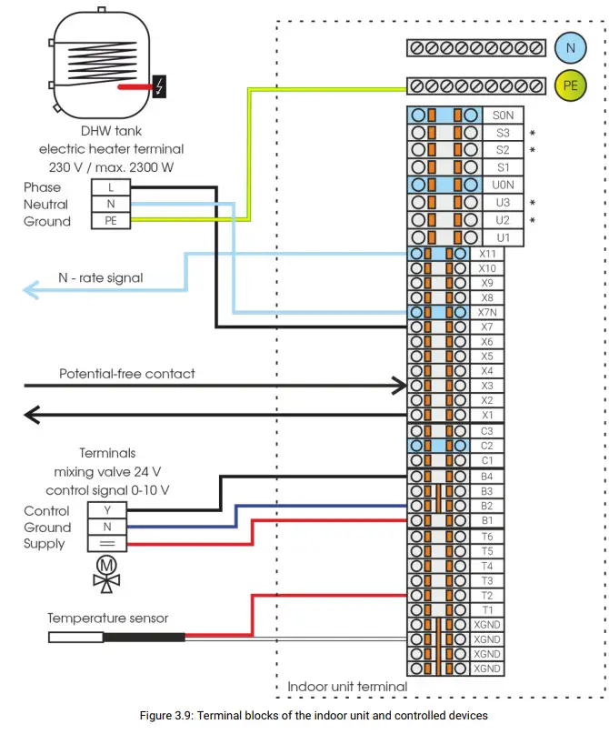
The diagram in the figure|3.9](p. 23) shows how the heater cartridge, control
relay and mixing valve are connected.
All connections must be secured against current overload.
3.7. Connection of the heat pump to the heating system
Three outlets are located on the bottom panel of the heat pump’s indoor unit.
Two outlets for heating water circuit and hot water circuit and one common
inlet for return water from both circuits.
Pictures [3.11] |3.12 (p. 25) schematically show recommended connections. The
minimum pipe dimensions are listed in the table. Each pipe connected to the
equipment must be provided with a fitting and a ball valve, as it provides the
option to shut down or dismantle the equipment. Also, on the return pipe, a
magnetic descaler with a filter must be installed in close proximity to the
device to protect the circulation pump and the plate heat exchanger from
damage due to occurrence of dirt in the heating circuit. Recommended strainer
thickness is 100 microns.
Sufficient heating pipe dimensions and sufficient hot water tank exchanger
surface are essential for proper opera- tion of the entire heating system.
Both of these values are shown in the following tables.
| Unit type | Main pipe diameter | Pressure loss |
|---|---|---|
| NeoRé 5,8, (HP) | 28 mm | 49kPa |
| NeoRé 14(HP) | 28 mm | 40kPa |
| NeoRé1 6 HP | 35mmm | 33 kPa |
Table 3.11: Main pipe diameter and pressure loss

| Unit type | Exchanger surface m2 |
|---|---|
| NeoRé | 1,8 |
| NeoRé 8, 8 HP | 2,5 |
| NeoRé | 3,2 |
| NeoRé HP, , HP | 4 |
| NeoRé 6 HP | 4,5 |
Table 3.12: Exchanger surface


3.7.1 Connection methods for:
Circulation pumps
Pumps without power control are used as circulation pumps in the system and
therefore, they are controlled only by power supply. Zero and protective
conductors are connected to PE and N bridges. The phase conductor is connected
to the terminal according to the location of the pump in the system.
Temperature sensors
Resistance temperature sensors of type PT1000/3850 must be used in the
system. These temperature sensors are connected between the XGND and X
terminals… according to the true placement in the system.
External bivalent source
In addition to integrated electric heaters with a total output of 6 kW, the
heat pump can also, in a passive way, control an external heat source. This
source may be an electric, gas, or other heat source equipped with input for
the control signal.
Alternatively, the source can be controlled by a pre-relay. The control is
done passively and it means that the bivalent source has its own regulation
and safety elements for operation and at the time when performance is
required, it reacts to the 230 V signal from terminal X1. If higher power is
required, the signal is also on terminal X2. The maximum output load allowed
IiS2A.
Mixing fitting
The mixer fitting may be used to connect the low temperature heating system
where an accumulation vessel is used to connect another high temperature heat
source or when low temperature and high temperature heating elements are used
within one installation. The mixing fitting must have a 24 V operating voltage
and a 0-10 V control signal. Terminals B1 and B2, which are a 24 V supply, are
designated to supply this valve. The output of the control signal is at
terminal B4.
3-way zone valve
A 3-way zone valve with a working voltage of 230 V is used to connect the
pool circuit. Zone valve power is supplied externally, for example, from the
switch cabinet for the pool technology. The control signal is taken from the
X5 terminal.
2-way zone valve
A 2-way valve could be used when you would like to use cooling function
during summer time. You want to cool through ceiling system and wean floor
system. Valve in the distributor is activated by a signal 230 V and close the
distributor. The control signal is taken from the X10 terminal.
Photovoltaics (PV)
In controller version 4.1.1 and higher, communication with photovoltaics is implemented. The AUX output of the PV is connected to the DI9 input and connected to AGND, in service setting 2 you turn on PV and you can set the cancellation of the DHW ptimization at the signal from the PV (PAGE166.XML – option Optimization by PV). PV optimization settings for heating/cooling are made in Settings – 3rd screen – PPV settings (PAGE171.xml), where it is possible to turn on PV optimiza- tion and PV opti-limit. You can find more information about photovoltaic settings in the User Manual chapter Description of the user interface.
When setting PV opti-limit % to:
0 – the outdoor unit is stopped and runs only when there is a signal from the
PV system
20 – when there is no PV signal, the output of the outdoor unit goes up to 20
%, i.e. up to the set FVE opti-limit value (during this operation, the
bivalent does not turn on, it is blocked)
20 – when the FVE signal is present, the output of the outdoor unit is
controlled up to the maximum output of the outdoor unit (PAGE71.XML)
3.8 Unauthorized connections to the heating system

Commissioning
4.1 Commissioning of the heating system
Before starting the circulating pump, the circuit must be filled with water.
Water should be filled to a basic pressure of 1-1.5 bar. From a water column
height of 14 m, the basic pressure increases by 0.1 bar per metre of height.
The maximum water column height is 18 m. The maximum operating pressure is 2.1
bar. After increasing the pressure, the circuit must be completely vented.
Venting of the indoor unit can be performed on the upper right side of the
plate exchanger. After starting the circulating pump, the plate exchanger must
be completely vented, which is indicated by smooth running of the circulating
pump. Before starting the compressor, it is recommended to let the circulating
pump run for at least 10 min.
For more information, see the Installation Manual, Chapter Connection of the
heat pump to the heating system.
4.2 Activation
After filling and venting, you can test the electrical equipment of the
heat pump.
Switch on the TECHNOLOGY circuit breaker and, after the controller system
initializes, press the H/C button in the “Overview” section. This activates
the circulating pump. Check the state of the hydraulic system. If the flow and
pres- sure are OK, you can switch on the remaining circuit breakers. Check the
settings and check the operation of all heat pump devices, especially the
outdoor unit (for DHW heating settings, see the DHW chapter in the User
Manual).
- OUTDOOR UNIT – outdoor unit circuit breakers
- TECHNOLOGY – circuit breaker of the indoor unit (control, 3-way valve, circ. pump…)
- DHW EL. HEATER – circuit breaker of DHW heatingv

Shutdown
Attention! When shutting down the system completely, the heating system and the heat pump can be damaged or completely destroyed in winter due to freezing.
5.1 Short-term shutdown
If you need to turn off the heat pump briefly, press H/C and/or DHW so that
the orange indicator in the upper right corner of the button turns grey. Do
not turn off the heat pump using the circuit breaker! The circulating pump
turns off 15 minutes after the operation is switched off. To reactivate, use
again H/C ( DHW )
5.2 Long-term shutdown
If you need to turn off the heat pump for a long time, press H/C and/or DHW so
that the orange indicator in the upper right corner of the buttons turns grey.
Do not turn off the heat pump immediately using the circuit breaker! The
circulating pump turns off 15 minutes after deactivation. You can then switch
off all circuit breakers. When shutting down the system for more than 6
months, you must switch on the TECHNOLOGY circuit breaker after this time and
leave it on for at least 24 hours. Otherwise, the backup battery may be
depleted and all user settings may be lost. When shutting down the system e.g.
from spring to autumn, we recommend using the method described in Chapter |5.1
— Short-term shutdown (page [31).
The heat pump consumes only 13 W of energy and the circulating pump regularly
flushes the heating system. This reduces clogging and the possibility of the
circulating pump being jammed.
Faults and status messages
6.1 Error code structure
A fault code consists of four digits. The first two digits indicate critical
errors. These are faults that cause the heat pump to stop running. The other
two digits indicate the status of the connected temperature sensors. Faults of
temperature sensors do not affect the operation of the heat pump. However, the
lack of information may decrease the quality of control and impair thermal
comfort inside the building.
6.2 Overview of faults and status messages
The following section describes what values the fault codes can have and what
these values mean. When reading the code, we proceed from left to right. The
order of the digits determines their meaning.
1 st digit
0 – No fault
- – Frost protection (the output water temperature dropped below the safe level)
- – Insuffcient flow (the water flow through the heat pump dropped below the minimum level)
- – Fault of the outdoor unit or communication
- – Low water pressure (the water pressure in the system is lower than 0.8 bar)
- – Faulty temperature sensor of the MX communication unit
- – Exceeding the bivalent weekly time limit
- – Refrigerant leak detection
If the value of the first digit is not 0, the heat pump stops running.
2nd digit
0 – No fault
1 – Faulty temperature sensor of heating (output) water – the sensor is
disconnected
2- Faulty temperature sensor of heating (output) water – the sensor is short-
circuited
3 – Faulty temperature sensor of return (input) water – the sensor is
disconnected
4 – Faulty temperature sensor of return (input) water – the sensor is short-
circuited If the value of the second digit is not 0, the heat pump stops
running.
3rd digit
0 – No fault
- Faulty outdoor temperature sensor — the sensor is disconnected
- Faulty outdoor temperature sensor — the sensor is short-circuited
- Faulty building temperature sensor — the sensor is disconnected
- Faulty building temperature sensor — the sensor is short-circuited
- Faulty DHW temperature sensor — the sensor is disconnected
- Faulty DHW temperature sensor — the sensor is short-circuited
- Faulty storage tank temperature sensor — the sensor is disconnected
- Faulty storage tank temperature sensor — the sensor is short-circuited
If the value of the 3rd digit is not 0, some of the sensors are defective and
the quality of temperature control may be reduced. However, the operation of
the heat pump is uninterrupted.
4th digit
0 – No fault
1 – Faulty pool temperature sensor — the sensor is disconnected
2 – Faulty pool temperature sensor — the sensor is short-circuited
3 – Faulty secondary circuit temperature sensor — the sensor is disconnected
4 – Faulty secondary circuit temperature sensor — the sensor is short-
circuited
If the value of the 4th digit is not 0, some of the sensors are defective and
the quality of temperature control may be reduced. However, the operation of
the heat pump is uninterrupted.
6.3 Faults and troubleshooting
lf the heat pump signals any of the critical errors (any of the first two
digits is not 0), it stops operating. The following text describes typical
causes of these errors and how to correct them. If the application of these
procedures is not successful, contact a service organization, which will take
care of your problem.
During the operation of the heat pump, cooling of the heat exchanger of the
outdoor unit causes it to freeze. When the evaporator is frozen, the outdoor
unit automatically evaluates this state and starts the defrosting process. The
frequency of defrost cycles depends on several factors, the most important of
which are air temperature, humidity and required power.
During the evaporator defrosting process, the evaporator is reheated using the
energy stored in the heating water and at the same time the fans start running
at full speed, which dries the evaporator. During this process, you can see
water vapour rising from the evaporator, which may seem like the unit is
burning. However, in this case, it is not a dangerous state but a normal
operating condition, so do not disconnect the outdoor unit from the power
supply.
The heat pump user interface in the States and faults lists the last ten fault
states (codes) of the heat pump.
Complete operating data is accessible via the heat pump’s web interface.
The controller has the Fault autoreset function. Thanks to this function, the
heat pump can resume operation after a critical fault has been removed, e.g. a
sufficient system flow restored. If the autoreset is activated 5 times, it is
clear that this is not a random fault. The heat pump remains in a fault state
and requires professional atten- tion. The autoreset function can be restored
inthe States and faults section, which should only be done after consultation
with a service organization.
Fault 1xxx
Frost protection. A fault occurs if the output water temperature is lower than
the safe limit. The default limit for frost protection is 15 °C. When the
output water temperature is lower, the heat pump stops running until the
output water temper- ature reaches a safe level again. Meanwhile, bivalent
operation is started. The heat pump starts 30 minutes after reaching a safe
temperature.
This fault typically occurs when the system is started, when the system is
filled with cold water from the water main.
Another typical situation where this fault occurs is the cooling of the
heating water during the defrosting process of the outdoor unit. This can have
two causes.
- Low temperature of heating water (below 25 °C) in the system, where heating water does not carry enough energy to defrost the outdoor unit.
- The second possible cause is a reduced flow of heating water through the heat pump, e.g. due to a clogged heating water filter.
If the frost protection fault occurs repeatedly, contact a service organization.
Fault 2xxx
Insufficient flow. The insufficient heating water flow fault occurs when the
current water flow is lower than required. The value of the required flow
directly depends on the current power of the outdoor unit, i.e. the higher the
power of the outdoor unit, the higher the required value of the heating water
flow. This is also the reason why the fault can occur seemingly randomly, e.g.
only when heating the heat water tank, when high power and therefore high
heating water flow is required.
A typical cause of a flow fault is clogging of the heating system with dirt.
The second possible cause is that the heating system contains a constricted
point. This point with an insufficient cross-section (e.g. control valve)
affects the total flow, even if the cross-section of all other parts of the
heating system is sufficient. Random and short-term faults can also be caused
by aeration of the heating system or low pressure of heating water.
All these cases require the attention of a service organization, which locates
and eliminates the cause of the fault.
Fault 3xxx
Fault of the outdoor unit or communication. The outdoor unit signals a fault
state. If this fault occurs once, it is advisable to try to restart the entire
system by switching off all heat pump circuit breakers and switching them on
again. If the outdoor unit or communication fault persists after the user
interface restarts, call a service organization.
Fault 4xxx
Low water pressure. If the heating system pressure is lower than 0.8 bar, the
device stops operating in order to avoid damage to the circulating pump.
The usual cause is leaking heating water. There may also be damage to the
expansion vessel or air leak from its bag. To remove the fault, increase the
water pressure in the heating system to 1.1-1.5 bar.
lf the pressure drop reoccurs, contact a service organization.
Error 4000 may also result in a clogged pressure sensor restrictor. This
sensor has a millimetre hole as protection against pressure shocks of the
sensor. If water contains too many free minerals, they settle on this hole and
block the sensor. The hole must be cleaned and the heating water quality
checked and, if necessary, improved.
Fault 5xxx
Faulty temperature sensor of the MX communication module. This fault means
that the temperature sensor of the out- door unit exchanger exhibits values
outside the valid range and it is apparently faulty. For this reason, the heat
pump stops running, as the loss of information about the exchanger temperature
may lead to its damage.
In the event of this fault, contact a service organization.
Fault x1xx a x2xx
Faulty temperature sensor of output water. If the heating water temperature
sensor fails, the heat pump stops running, because the indoor unit can be
damaged due to an unknown temperature of output water.
The temperature sensor must be repaired or replaced with a new one, so contact
a service organization.
Fault x3xx a x4xx
Faulty temperature sensor of return water. If the return water temperature
sensor fails, the heat pump stops running, because the indoor unit can be
damaged due to an unknown temperature of return water.
The temperature sensor must be repaired or replaced with a new one, so contact
a service organization.
Fault 6000
If the bivalent weekly limit is exceeded, the auto-reset of errors will be
disabled and the machine will stop. Can be reset by turning on the Autoreset
switch. This will also reset the counter. The limit value in hours is set in
the service menu. Preset to 100 hours, when the limit is set to 168 hours, the
function is essentially inactive.
Fault 7000
The error is displayed if a refrigerant leak detector is fitted and there is a
leak of 60g/m 3 or more. Subsequently, the entire machine stops. In the event
of this failure, a service organization must be contacted.
6.4Status messages
Status messages are displayed in the same section as faults, but in the third
and fourth position when reading from the left. If the code of any status
message is active, it is only an informative message about the given fact. The
operation of the heat pump is not interrupted. The displayed states are sorted
by priority, where the number 1 has the highest priority. If state 7 is
active, it means that no status with a lower numerical value is active.
Status 0 means that all available temperature sensors are connected and
working correctly.
Status xx1x and xx2x
This status means that the outdoor temperature sensor is disconnected or
faulty. When operating without an outdoor temperature sensor, the output water
temperature is not controlled according to the set weather compensation curve,
but is heated continuously to the temperature set by the weather compensation
curve for an outdoor temperature of +19 °C. To correct this, contact a service
organization.
Status xx3x and xx4x
This status means that the indoor temperature sensor is disconnected or
faulty. The indoor temperature sensor is not a standard part of the heat pump
installation and it is therefore possible that this status will be displayed
permanently.
When operating without an indoor temperature sensor, the automatic weather
compensation curve correction function is not available, but the heat pump
operation is not interrupted.
To repair or add the temperature sensor, contact a service organization.
Status xx5x and xx6x
This status means that the DHW tank temperature sensor is disconnected or
faulty. When operating without a DHW temperature sensor, the tank will not be
heated.
To correct this, contact a service organization.
Status xx7x and xx8x
This status means that the storage tank temperature sensor is disconnected or
faulty. If the storage tank is not part of the heat pump installation, this
status may be displayed permanently. When operating the heat pump with a
faulty storage tank temperature sensor, storage tank heating will be stopped
until the fault is removed. Other functions of the heat pump remain unchanged.
To correct this, contact a service organization.
Status xxx1 and xxx2
This status means that the pool circuit temperature sensor is disconnected or
faulty. If your installation includes a pool water heating circuit, the
heating will be stopped until the fault is removed. However, other circuits of
the heat pump remain unchanged.
To correct this, contact a service organization.
Status xxx3 and xxx4
This status means that the secondary circuit temperature sensor is
disconnected or faulty. If your installation includes a secondary heating
circuit, this circuit is stopped until the fault is removed. However, other
circuits of the heat pump remain unchanged.
To correct this, contact a service organization.
6.5 Protective functions
All protective functions are active only when the indoor unit is powered and
device circuit breakers are on.
These are protective mechanisms that take care of the safety of the heat pump
and protect it from damage or destruction. The following overview lists and
explains these safety functions. This list primarily aims to explain the
behaviour of the heat pump to the end user or to aid a service organization.
In no case it encourages making changes to the product itself or in the
service offer. Improper handling can damage or destroy the product.
Frost protection — static (output water temperature)
If the indoor unit is powered, the temperature of the indoor unit’s output
water sensor is monitored. If the water tempera- ture drops below +5 °C, it
activates the circulating pump and the first stage of the integrated bivalent
source (2 kW). As soon as the water temperature in the heating system rises
above +5 °C, both the circulating pump and the bivalent source stop.
This protection is active even if heating is turned off.
Frost protection — during operation
If during operation (heating) the temperature of output water drops below the
set value (the default value is 11 °C), the outdoor unit stops and the
integrated bivalent source activates to heat the heating water. After
achieving an output water temperature of 11 °C, the bivalent source keeps
heating the heating water for another 30 minutes. After this period, the
device keeps operating as standard with the outdoor unit.
This protection usually activates when the outdoor unit is defrosting and the
flow is insufficient (or when there is low thermal energy in the system).
The value can be set in the service settings as parameter T frost. This
protection is linked to the autoreset function.
Flow monitoring — monitoring depending on the outdoor unit power
To maintain the declared efficiency of the heat pump and safe operation, it is
necessary to maintain a sufficient flow of heating water. The minimum flow is
given by the relationship between the outdoor unit power and the required
power of the circulating pump. Values of minimum flow for individual types of
heat pumps are listed in the table in ch. “Design documents”.
This protection is linked to the autoreset function.
Flow monitoring — monitoring of critical flow
If during the operation of the circulating pump the flow value drops below 300
I/h (fixed value) or below the min. flow according to Figure Minimum water
flow for individual power types in the /nstallation Manual, ch. Hydraulic
Circuit, a flow error is triggered and the circulating pump automatic venting
program is started.
Venting is performed in cycles, where in each cycle the circulating pump first
idles for 10 seconds and then works at full power for 10 seconds. These cycles
are repeated continuously until the required minimum flow value is achieved.
Flow monitoring — flow change during defrosting and cooling
When the outdoor unit is defrosting, the power of the circulating pump is
automatically increased to 100 %. If the heat pump is switched to cooling, the
circulating pump is not controlled proportionally, but continuously running at
full 100 % power.
Water pressure monitoring — heating/cooling water pressure
The loss of pressure in the heating system is a serious problem, so when
the pressure in the heating system drops below the set value, the entire
system stops.
The critical pressure value can be set in the service settings under Minimum
water pressure.
This protection is linked to the autoreset function.
Sensor monitoring — critical sensors
The operation of the heat pump requires two temperature sensors. The output
water temperature sensor and the returnwater temperature sensor. If the values
indicated by the sensor fall outside the range (-50 °C to +120 °C), the heat
pump stops.
This protection is linked to the autoreset function.
Sensor monitoring — other sensors
A fault of other non-critical sensors is only signalled. It does not affect
the primary operation of the heat pump. It affectsonly the relevant section to
which the temperature sensor belongs. For example, if the DHW sensor shows a
fault, DHW heating will be interrupted.
Outdoor unit failure
A fault of the outdoor unit is only signalled. It does not affect the primary
operation of the heat pump. If the outdoor unit supplies insufficient or no
power, the system automatically uses the integrated bivalent source and
signals a fault of the outdoor unit.
Compressor heating
After switching on the heat pump or restoring its power after an outage, only
the bivalent source is used for a certain time. During this time, the outdoor
unit is in compressor box heating mode.
By default, this protection is not active (set to zero time), but it is
recommended to set this protection in installations where longer power outages
often occur.
This protective function can be set in the service settings under “Delayed
start”.
Output water temperature limits
It limits the user setting of desired temperatures to a pre-set range. The
range can be set in the service settings un- der Minimum output water
temperature and Maximum output water temperature . The default values are 20
°C for minimum temperature and 60 °C for maximum temperature.
Restart
Protection of the compressor against frequent starts that happen during unit
cycling. This occurs when the minimum power that the heat pump can deliver is
higher than the instantaneous loss of the building. This function prevents
overly fre- quent starts and thus prolongs the service life of the compressor.
The default setting is 10 minutes and 5 %. This means that the outdoor unit
starts up again after 10 minutes at the earliest and after an increase in the
outdoor unit power requirement by more than 5 %.
Both parameters can be set in the service settings as Restart and Restart
Threshold.
Cooling water temperature deficit
Protection against low water temperature during cooling, when the cooling
water temperature drops below the set limit.
The limit temperature for shutting down the outdoor unit and cooling is set as
the cooling water temperature minus the cooling water temperature deficit.
After the output water again reaches a higher temperature than the set cooling
water temperature, the heat pump resumes cooling.
The Cooling water temperature deficit parameter can be changed in the service
settings.
Fault autoreset
Automatic resumption of operation after some faults have subsided is a
function that helps eliminate random problems on the device. It can
automatically restore operation up to 5 times. If the fault or faults occur
more than 5 times, the operation of the heat pump will not be resumed until
the operator or service technician has intervened.
Maintenance of the device and components
Thanks to its design, the heat pump is easy to maintain. Basic maintenance is
to be performed by a service organization during regular annual inspection.
During this inspection, the service organization shall check all important
parts of the heat pump, especially the operation of the refrigerant circuit.
Regular inspections and maintenance of the indoor and outdoor unit of the heat
pump and heating system help pre- vent more serious faults and damage. We
recommend having a service organization perform a general inspection once a
year.
To maintain correct and, above all, efficient operation, we recommend checking
the condition of the whole system at least once a month. This means checking
the indoor unit display for a fault or abnormal sounds or behaviour.
Similarly, make sure the outdoor unit is operating correctly and does not make
unusual noises. It is also important to check the condition and cleanliness of
the outdoor unit exchanger and regularly check the state of the hot water
tank.
7.1. Maintenance of the outdoor unit
For proper function and the required efficiency, make sure that the outdoor
unit always has good air access. Therefore, it is necessary to regularly check
the condition of the fin heat exchanged for clogging, e.g. by leaves/blossoms
fallen from trees, dust, snow or ice. Clean the fin exchanger carefully with
non-pressurized water. The fins are very fine and could be damaged. The
refrigerant and electrical system may only be inspected by a certified service
technician.
If the unit is snow-covered so that the snow prevents the air from flowing
freely, remove the snow. If the evaporator is covered with a layer of ice,
remove this ice by pouring hot water over it until all the ice has melted.
Do not use high-pressure cleaners or any mechanical aids (brushes, etc.).
Before cleaning the fins of the outdoor unit, switch off the main circuit
breaker in the indoor unit!
Maintenance and cleaning of all components must be performed in the non-
powered state.
If the outdoor unit exchanger is obstructed (dust, leaves, ice) or the entire
outdoor unit is covered with snow, the device loses power, efficiency, or
cannot be operated at all.
7.2 Maintenance of the indoor unit
The indoor unit requires only minimum maintenance. The device does not contain components that require maintenance by the user. Use only a damp cloth to clean its surface. Take extra care when the device is in operation and powered. We recommend performing maintenance on the indoor unit outside the heating/cooling season in the non-powered state.
We recommend having the entire heat pump inspected regularly once a year by a
service technician of the installation company.
Maintenance and cleaning of all components must be performed in the non-
powered state.
7.3. Maintenance of the DHW tank
To maintain the correct and, above all, efficient operation of the DHW tank,
check the sediment content in the tank at least once every 2 years. Once every
two years (once a year for stainless steel tanks), also check the condition of
the anode rod and replace it if necessary.
In addition, observe the requirements of the tank manufacturer.
7.4 Maintenance plan
Design documentation
8.1 Connection of the heat pump to the heating system
Designing
The impact of the quality of the heating system design is as important as the
influence of the quality of water or ma- terials used. Insufficient heat
transfer fluid flow leads to an increase in condensation temperature and thus
a significant deterioration in COP. A poorly designed control system has the
same effect. Conversely, high flow rates lead to corrosion and erosion.
Insufficient size of the expansion vessel is directly related to the
possibility of corrosion of the heating system.
Installation and commissioning
Seemingly insignificant changes during execution, compared to the project, can
lead to the condition that the heating system is defect-prone. Joint quality,
welding and soldering procedures, flushing and first firing are the
cornerstones of user satisfaction. Installation of the heating system with
non-qualified people, in order to save costs, is an intolerable risk.
Used materials and equipment
This issue basically depends on the heating system design. The designer
should refrain from solutions where the result is a material-mixed system,
e.g. copper pipes, aluminum radiators, steel boiler. In real life, such a
system cannot be protected against different types of corrosion. It is always
worthwhile to use materials with appropriate certification. This also applies
to auxiliary materials such as seals, fluxes and solders. A common cause of
overall corrosion of the heating system is the use of plastic pipes without
oxygen barrier for underfloor heating.
The quality of circulation water
The circulation water quality is decisive for the long-term trouble-free
operation of the heating system. The properties of water used as the heat
transfer fluid vary different depending on the location of the borehole and
water sources. It is necessary to realize that water, which in all parameters
corresponds to drinking quality, usually does not suit heating systems without
treatment. For heating systems, it is important to know parameters such as
hardness, salinity, acidity and dissolved gas content in water.
The water hardness determines the amount of Ca2+ a Mg2+ salts contained,
which, by varying the solubility under oper- ating conditions, form virtually
insoluble carbonates. Scale is excreted predominantly on the bivalent source
and exerts its negative effects by the following mechanism. At the beginning,
it creates a compact thermal insulation layer. This reduces the overall output
of the source and also causes local overheating of the exchanger. Due to
uneven dilatation at the over- heating area, the compactness of the layer is
impaired. Pieces of the limescale peel off and get into the circulating water
and gradually clog both the refrigerant exchanger and the control valves.
During limescale formation, carbon dioxide is released, causing aeration of
the system and, under favourable conditions, surface corrosion. In addition,
it is necessary to replenish missing water which is largely untreated and re-
injects unwanted influences into the system.
The salinity is the sum of all dissolved salts in the water. In practice,
these are Na+, K+, Fe2+ cations and Cl- and SO42- anions. Fe2, Cl- and SO42-
ions pose danger as they support the heating system corrosion processes. Water
salinity is directly proportional to its electrical conductivity. High water
salinity promotes electrolytic corrosion, especially when using various types
of metals (copper, iron).
An important criterion for the corrosion behaviour of the system is its
acidity – pH. In order to minimize the corrosive effect of water, pH should
correspond to the materials used. For example, it is important to note that a
steel-compliant pH does not suit aluminum and vice versa.
The content of dissolved gases in water depends on its temperature and gas
pressure. For heating water, relevant air contains mainly Nz, O2 aCOz.
Nitrogen, from the chemical regime point of view, is harmless, but from the
operational point of view has an adverse effect, decreases the temperature
capacity of water, increases compression work and causes cavitation noise.
Oxygen and carbon dioxide are corrosive and need to be removed from water.
Most of the dissolved gases can be removed from the heating system by
deaerating. However, it is not possible to remove gases from the circulating
water completely.
When properly vented, this is a relatively small amount of gas whose effects
do not have a major impact on the long service life and reliability of the
heating system. Residual oxygen and carbon dioxide are consumed in corrosion
reactions and consequently corrosion ceases. The greatest danger is when
oxygen enters into the system repeatedly. In practice, this is the most common
cause of corrosion of the heating system. The reason may be a leak in the
system, unsuitable parameters of the expansion vessel, the quality of the
sealing elements and the used plastic elements. Beware that for instance
underfloor heating made of plastic piping with oxygen barrier corresponding to
the regulation does not form a 100% oxygen diffusion barrier. In this case,
oxygen enters the system repeatedly and the corrosion processes do not stop
spontaneously. Here, it is necessary to repeatedly use preparations that bind
the oxygen in question.
Principles for commissioning and operating a hot water heating system In
modern hot water systems, inadequate care for the quality of filling and
circulating water, or installation, commis- sioning, and operation becomes
clearly evident very soon. The aim of this text is to highlight the principles
related to this issue.
-
The quality of filling and circulation water – Valid standard dealing with water quality CSN 07 7401 is obligatory for hot water systems up to 115 °C ° with nominal output higher than 60 kW. Water according to this standard is also fully suitable for systems with lower output. However, the treatment of water to the extent given by this standard for small systems (flats, family houses) is not realistic in practice.
Generally recommended operating water parameters:
• pH 6,5-8,5
• conductivity up to 350 us/cm
• hardness 2 – 6 °dH
• NO bacteria
• No mechanical impurities
Steel corrosion:
• at pH above 8.5 satisfactory
• at pH above 10 is negligible
Copper corrosion:
• at pH above 10 is considerable
• at pH between 8.5 to 9 is moderate
Aluminum corrosion:
• at pH above 7.5 is considerable
• at pH 6.5 to 7.5 is acceptable
•when using drinking water, it is necessary to dispense chemicals against corrosion and to stabilize water hardness
• for material-mixed heating systems (steel, copper, aluminum), it is necessary to chemicals that are specifically de- signed for the given system
•check the chemical content at least once a year (before the heating season) and refill, if necessary -
Flushing out a new heating system = – The CSN 06 0310 standard for central heating design and installation according to Article 132 prescribes flushing the equipment before testing and commissioning. The purpose of this obligation is to remove unwanted impurities from the heating system. These are mainly mechanical impurities, fats and oils, residual products after welding and soldering.
– if possible, use softened water (max. 5.6 NO), drinking water without treatment is also applicable
– dispense suitable non-foaming degreasing agent for removing grease and oils according to the instructions for use in the filling water (cold or warm water alone does not remove oil and grease)
-
set the maximum circulation water flow (open control valves, pump capacity set to maximum)
-
heat the heating system by half output of the boiler to about 6 °C (keep slow temperature rise especially when non- softened water is used to minimize scale formation)
-
operate the system for about 1/2 hour after heating the water
– after cooling the system to approx. 40 °C, drain rinsing water out, while observing the regulation about waste water – clean filters from mechanical impurities – without delay, fill the system with permanent filling- Setting the pressure expansion vessel parameters – The selected volume and pressure parameters of the expansion vessel are important for long-term trouble-free operation of the heating system. The required volume of the pressure ex- pansion vessel is determined according to CSN 06 0830. Insufficient volume and unsatisfactory pressure conditions of the expansion vessel lead to repeated aeration and corrosion of the heating system. The heating system designer should ensure the correct volume of the expansion vessel. We recommend that the installer sets the pressure parameters as follows. The user should check these parameters once a year.
Gas overpressure (Pn) in the expansion vessel
– when adjusting the gas overpressure, the expansion vessel must be without water
- Setting the pressure expansion vessel parameters – The selected volume and pressure parameters of the expansion vessel are important for long-term trouble-free operation of the heating system. The required volume of the pressure ex- pansion vessel is determined according to CSN 06 0830. Insufficient volume and unsatisfactory pressure conditions of the expansion vessel lead to repeated aeration and corrosion of the heating system. The heating system designer should ensure the correct volume of the expansion vessel. We recommend that the installer sets the pressure parameters as follows. The user should check these parameters once a year.
-
pressure Pn should be 0.2 bar higher than the static water column height (Pst) of the heating system (vertical distance between the expansion vessel and the highest point of the heating system — 1m = 0,1bar)
Filling water pressure setting (Pf) -
by opening all the control valves, allow the system to fill without problems
-
the filling water pressure Pf should be 0.3 to 0.5 bar higher than the gas pressure (Pn) in the expansion vessel. The filling water pressure is checked when cold with a pressure gauge on the water side after venting.
Adjusting safety pressure (Psv) -
the safety pressure Psv should be 0.5 bar higher than the operating pressure (Pe) of the system heated up to operating maximum. This is true when the safety pressure Psv <5 bar. If Psv > 5 bars, then Pe + 0,9 Psv. 4. Venting the heating system – Venting is a process that is repeatedly done upon filling, commissioning and operating the heating system. We recommend that you follow these guidelines:
– when filling the heating system, venting should be carried out continuously -
final venting to be carried out at maximum operating temperature of circulating water
-
carry out venting after approx. 5 minutes of standstill of the circulation pump at all deaeration points of the heating system
-
repeat venting after several days of operation 5. Hot water system commissioning – The system is filled with permanent filling (treated water according to point 1) and after successful leak test it is possible to commission the heating system. Adhere to the following principles:
• first heat up by slow start of the heat pump performance
• deaerate as described above
• conduct operational tests to the extent agreed between the investor and the implementer- Operation of the heating system – As a rule, the first season of operation is linked with the heating test and fine-tuning of the whole system. We recommend that you follow these guidelines:
• check the tightness of the heating system, do not react to water loss by mere water refilling
• check the filter clogging condition and if necessary, clean the filters
• drain the system only in case of necessary repairs and leave it empty only for as short as possible
• if there is a risk of freezing, the problem can be solved by using antifreeze and not by draining the system
• regularly check and maintain the individual elements (pump, boiler, control elements, expansion vessel) according to the relevant instructions for use
• check the quality of circulating water at the start of each heating season and add appropriate chemical agents as needed
- Operation of the heating system – As a rule, the first season of operation is linked with the heating test and fine-tuning of the whole system. We recommend that you follow these guidelines:
Technical options and chemicals for protection of hot water heating systems
The action of hard untreated water and the associated corrosion processes in
the heating system are generally known.
Therefore, there are a number of manufacturers of “chemicals and equipment for
heating system” for treatment of filling and circulation water, corrosion
protection and cleaning of already clogged heating systems.
The manufacturer is not authorized to recommend a specific agent. The
manufacturer and user share the responsibility for choice of agent, method of
application, technical effect and guarantee. When choosing “chemicals for
heating systems”, it is necessary to proceed very carefully, preferably after
agreement with the manufacturer. Only if you know the hardness and
aggressiveness of the filling water, the material composition of the heating
system (steel, cast iron, copper, plastic, aluminum and their various
combinations), a professional choice can be made for given type of heating
system (self-weight, forced circulation with expansion vessel, underfloor
heating. It is equally important to maintain the initial dosage, as well as
replenish the “heating system chemicals” during operation. A professional
product should be supplied with a methodology for determining its current
concentration in circulating water.
Another options of water treatment on cation exchanger or reverse osmosis
desalination are not applicable for small systems out of economical reasons.
For the same reasons, options of physical water treatment for small heating
systems narrow down to magnetic treatment that prevents scale formation.
A common question is how to get the “heating system chemical agents” into the
system. In addition to the inventiveness of the installers and operators,
there are professional flow-through containers for chemical dosing or pressure
pumps for refilling during operation.
The author of the chapter “Connection of the heat pump to the heating circuit”
of the installation manual: Ing. Jozef Gulyás Organization: KORADO a.s. Česká
Třebová
8.2 Hydraulic circuit
The NeoRé heat pump is designed to be as simple to install as possible. All
important elements of the hydraulic circuit are integrated in the indoor unit.
The indoor unit includes a powerful circulation pump, an exchanger, a three-
way zone valve for DHW charging, an 8-liter expansion vessel, a 6kW electric
boiler, a DN20 / 2.5bar safety valve. When designing a hydraulic circuit, it
is necessary to take into account the high demands of heat pumps for suficient
flow of heating water. The NeoRé heat pump can operate without an accumulation
vessel.
In this case, the following requirements must be met. The heat pump must not
be shut down from the heating system.
The heat pump must have enough heat energy that is taken back during
defrosting the outdoor unit. It is not recommended to use thermostatic valves,
by-pass with pressure differential valve or mixing valve (typically a four-way
valve).
lf a non-return valve must be used in a hydraulic circuit without a storage
tank, it is possible that the unit will report insufficient flow at low pump
speed. It is then necessary to increase the minimum possible speed of the
circulation pump according to the situation. The temperature control of
heating water for the heating system is determined by the equithermal
regulation that is a part of the indoor unit control system. If it is
necessary to use control elements that control more than 25% of the heating
water flow, it is necessary to use an accumulation vessel. In no case is it
recommended to use a hydraulic dynamic pressure equalizer (torus) to connect
the heat pump to the heating system. Use of the equilizer, due to its
temperature gradient, impairs the efficiency of the heat pump significantly.
We only use an anuloid to connect a bivalent source (if needed) to the heating
water circuit.
When using a non-return valve, it is necessary to set the minimum circulation
pump output to 60% or according to the non-return valve behaviour.
lf an accumulation tank is used, it is necessary to ensure the same flow (at
least under full load) between the primary and secondary sides of the
hydraulic circuit. Recommended dimension of the accumulation tank (at least):
14.6 liters per kW heat pump output.
 A variable capacity circulation pump
is installed in the heat pump. The minimum flow, below which the heat pump
will be shut down, is shown in the following graph.
A variable capacity circulation pump
is installed in the heat pump. The minimum flow, below which the heat pump
will be shut down, is shown in the following graph.
 8.3
Heating – range of working temperatures
8.3
Heating – range of working temperatures
The NeoRé heat pump can operate only within the output water temperature range
according to the graph [8.3)- Working range of output water temperature. The
heating system must be designed according to these requirements.
The working temperature range must also be taken into account when heating an
unheated building (especially in the case of newly completed buildings in
winter) and during floor drying. Drying floors with underfloor heating in
winter using an air-water heat pump (especially without storage tank) is
problematic.
The heat pump must have sufficient heat energy in the heating system during
defrosting. This energy must be in the temperature level according to the
graph of working range.
For drying floors in winter, it is allowed to use the outdoor unit until a
part of moisture is removed from the floor and the return temperature reaches
the working range. This can be achieved by an initial heating using then
electric boiler only. (The outdoor unit stays off at the breaker)

Figure 8.3: Outlet water working temperature range
When drying floors with underfloor heating in winter, a large amount of energy
is consumed (depending on the size of the building) and it is expensive.
Especially if you use inappropriate electricity rate (e.g. DO1d rate).
8.3.1 Floor drying program
Floor drying screen (Fig. 8.4) is divided into two parts, the left for
adjusting and the right for control.
Five time periods can be selected in the table on the left of the screen,
while the output water temperature and time range for which the temperature is
to be maintained, can be selected for each period. The individual time slots
follow each other, and after entering the end time of one section, the start
time of the next section is automatically adjusted. The total time of floor
drying can be up to 480 hours.
At the top right of the screen, there is Counter status , which shows how many
hours of the floor drying process have passed and the currently set output
water temperature.
There are two switches under this information. The switch Drying activates the
floor drying process. With the same switch, the running process can be paused
and restarted. The second switch Reset timer resets the floor drying process
timer and can be restarted.

Drying floors with the heat pump in winter can only be started when the return
water temperature exceeds 20°C. Other- wise, if you do not have another heat
source, you must use a built-in or external electric boiler.
Failure to follow this advice will cause the heat pump to malfunction and it
can result in damage.
The drying program in the heat pump is only a tool to simplify the drying
process. When drying, it is always necessary to comply with the requirements
of the floor technology supplier (floor screeds, floor coverings, etc.). It is
also necessary to monitor the humidity level in the building so that it cannot
result in damage of the building or its internal equipment (plasterboard
ceiling, electrical equipment, wooden interior elements, etc.).
Floor drying must always be coordinated with other suppliers.
8.4Cooling – range of working temperatures
The NeoRé heat pump can only be operated in cooling mode if there is no water
condensation on any element of the cooling system. It is therefore only
suitable for large area cooling systems such as cooling ceilings, etc.
The flooring system can also be used for cooling, but a very limited cooling
capacity of such a system is to be expected.
The recommended cooling water temperature is 19 to 22 °C, provided this
temperature is outside the condensation zone.
The maximum range of cooling water temperatures is 18 to 25 °C.
The general recommendation is to use cooling ahead of expected high outdoor
temperatures and use cooling without interruption.
In the case of use with cooling ceiling systems, a self-regulating effect
occurs where the cooling capacity of the system depends on the temperature
gradient of the ceiling surface and the room temperature. This maintains the
natural tempera- ture difference between the outdoor temperature and the room
temperature.
In applications with the probability of dew formation due to exceeding the dew
point, it is necessary to use a dew point sensor at the place where most dew
can be expected. In case of higher count of critical places could be used up
to four dew point sensors. Cooling water temperature is managed that it is
always 2 °C higher, than the highes dew point temperature.
The dew point sensor is set in the service settings item CIB sensor setting.
You can change the distance from the dew point (default value is 2) and enter
up to 4 sensors using the HW address.
8.4.1 Dew point table
| Room temperature °C
---|---
relative humidity %| 25| 26| 27| 28
50%| 13,8| 14,7| 15,6| 16,5
60%| 16,6| 17,6| 18,5| 19,5
70%| 19| 20| 21| 22
80%| 21,3| 22,2| 23,2| 24,2
90%| 23,2| 24,2| 25| 26,2
Table 8.1: Dew point temperature in ° C
8.5 Acoustic parameters
The following tables show the acoustic performance values of each outdoor unit
type in standard mode and in night attenuation mode (second table).
Furthermore, the acoustic pressure values for both modes in the model
environment and at varying distances from the outdoor unit are listed.
Acoustic power in standard mode
| Type | Acoustic power (dBA) | Acoustic pressure (dBA) |
|---|---|---|
| 1m | 3m | |
| NeoRe 5 TG MINI | 58 | 50 |
| NeoRe 8 TG MINI | 60 | 52 |
| NeoRe 11 TG MINI | 62 | 54 |
| NeoRe 14 TG MINI | 62 | 54 |
| NeoRe 8 TG MINI HP | 58 | 50 |
| NeoRe 11 TG MINI HP | 59,5 | 52 |
| NeoRe 14 TG MINI HP | 60. | 52 |
| NeoRe 16 TG MINI HP | 60,5 | 53 |
Acoustic power in silent mode
| Type | Acoustic power (dBA) | Acoustic pressure (dBA) |
|---|---|---|
| 1m | 3m | |
| NeoRe 5 TG MINI | 53 | 45 |
| NeoRe 8 TG MINI | 55 | 47 |
| NeoRe 11 TG MINI | 57 | 49 |
| NeoRe 14 TG MINI | 57 | 49 |
| NeoRe 8 TG MINI HP | 53 | 45 |
| NeoRe 11 TG MINI HP | 54,5 | 47 |
| NeoRe 14 TG MINI HP | 54,5 | 47 |
| NeoRe 16 TG MINI HP | 55,5 | 48 |
x – 1,5m ahead of outdoor unit may not be any barrier. Beacuse of this
acoustic pressure is not measured in distance of 1 m.
Figure 8.5: Acoustic parameters
Technical data
9.1Electrical wiring diagram of the indoor unit

9.2Hydraulic wiring diagram of the indoor unit

- Exchanger refrigerant/water
- Circulator
- Manual bleeding valve
- Pressure sensor 0-4 Bar
- Heating water outpu
- Return water inlet
- Howmeter
9.3Structural BOM

| Label | Description | Part number |
|---|---|---|
| 1. | Exchanger | 10002090001 |
| 2. | Output part | 10002090005 |
| 2. | Circulator | 10002090006 |
| 2. | Flowmeter | 10002090007 |
| 2. | Pressure sensor | 10002090008 |
| 2. | Control unit | 10002090009 |
| 1.10 | Low-voltage source | 10002090010 |
| 1.11 | MX communication | 10002090011 |
| 1.12 | Breaker (specification) | 10002090012 |
Figure 9.3: Structural BOM
9.4 Dimensions

9.5 Dimensions of the wall bracket (pad)

9.6 Removing the cover

Manufacturer contact
MANUFACTURER
NEOTACZs.r.o.
Stefanikova 75/8
602 00 Brno, Czech Republic
Company ID No. 27759431
VAT ID No. CZ27759431
ESTABLISHMENT
NEOTA CZ s.r.o.
Jankovice 133
769 01 Holesov, Czech Republic
Phone: +420 730 894 300
E-mail: support@neota.cz
f facebook.com/tepelnacerpadlaneore
f facebook.com/firmaNEOTACZ
10.1 Documents for download
All product documentation is also available online at
www.neota.cz/en/downloads in PDF format.
10.2 Online manuals
For quick access to manuals from you cellphone you can use QR codes.
|
---|---
https://manual.neota.cz/neore-tg/NO_NeoRe_TG-
MINI23_user.pdf| https://manual.neota.cz/neore-tg/EN_NeoRe_TG-
MINI23_installation.pdf
Documents / Resources
| NeoR
TG MINI Heat Pump Air
Water
[pdf] Instruction Manual
TG MINI Heat Pump Air Water, TG MINI, Heat Pump Air Water, Air Water, Water
---|---
Read User Manual Online (PDF format)
Read User Manual Online (PDF format) >>