FSR INC DV-HMSW4K-44 4×4 HDMI 4K Matrix Switcher User Manual
- June 12, 2024
- FSR INC
Table of Contents
- SURGE PROTECTION DEVICE RECOMMENDED
- POWER SUPPLY VOLTAGE WARNING
- Features
- What’s in the box
- Specifications
- Panel Descriptions
- Connecting and Operating
- Application Diagram
- Remote Control Description
- RS232 Pin Assignment
- RS232 Software Control
- Command Control
- Web GUI Control
- Controlling the Matrix via the WEB GUI
- Limited Warranty
- Customer Support
- References
- Read User Manual Online (PDF format)
- Download This Manual (PDF format)
FSR INC DV-HMSW4K-44 4×4 HDMI 4K Matrix Switcher

SURGE PROTECTION DEVICE RECOMMENDED
This product contains sensitive electrical components that may be damaged by electrical spikes, surges, electric shock, lightning strikes, etc. Use of surge protection systems is highly recommended in order to protect and extend the life of your equipment.
POWER SUPPLY VOLTAGE WARNING
This unit is equipped with a 5 volt power supply. Use only the correct, center positive 5 volt supply or damage to the unit itself and any connected equipment may result. Damage caused by incorrect power supply voltage or polarity is not covered under the warranty.
Features
- HDMI 2.0 and HDCP 2.2 compliant device supports up to 4K @60Hz YUV 4:4:4 HDR Bandwidth up to 18Gbps
- HDR supports high dynamic range 10bit (HDR10)
- HDCP2.2 input ,HDCP2.2 output
- HDCP1.4 input, HDCP1.4 output
- 4xHDMI Input, 4xHDMI output with 4xSPDIF Audio
- Any one of the 4 Ultra HD sources to any one of the 4 Ultra HD displays
- Supports Panel Button, Local IR, RS232 Control with command, IP Control, Web GUI Control
- Supports Dolby True HD and DTS-HD master audio, Dolby Atmos under copy EDID mode Supports firmware updating through USB port
- Unit size: 8.5”W x 4.2”D x 1.38”H (Not including connectors)
What’s in the box
- 1x HDMI Matrix
- 1x 5V DC power supply** See Caution on page 2
- 1x Remote control
- 1x IR Ext RX Cable
- 1x Phoenix plugs for RS232 cable termination
- 1x mounting kit
- 1x CD for control software & user manual

Specifications
| Operating Temperature | 23°F to 113°F (-5°C to 45°C) |
|---|---|
| Storage Temperature | -4°F to 140°F (-20°C to 60°C) |
Resolution
| 480p@60hz,576P@50hz,720P@60hz,
1080P@24hz,1080P@50hz,1080P@60hz,4K@24hz,4K@3
0hz,
4K@60hz YUV4:2:0, 4K@ 60hz YUV4:4:4 HDR (HDR10)
HDCP Compliant| HDCP2.2 and HDCP1.4
Output Video| HDMI2.0 and HDMI 1.4
Audio Format Supported| PCM, Dolby5.1/7.1, DTS5.1/7.1 digital audio, Dolby
Atmos
RS-232 serial port| 3PIN terminal block connectors
Ethernet port (IP control)| RJ45, female
IR Ext port| 1×3.5mm stereo jack
USB port| Micro 5P female
Bandwidth| 18 Gbps
Default IP| 192.168.1.168
Rack-Mountable| Rack ears included
Chassis dimensions(WxHxD)| 8.5”W x 4.2”D x 1.38”H (Not including connectors)
Shipping dimensions (carton):| 10”W x 8”D x 1.5”H
Shipping weight| 2.35 lbs. / 1.06 kg
Power consumption| 13W (Max)
Panel Descriptions

➀ IR receive window.
➁ Output button OUT1~4: choose the desired output port from input ports 1~4.
- Note: 1) Turn on/off DHCP function: press the selector of output 1 and output 2 for 3 seconds.
- Restore factory settings: when all outputs select input 1, press the selector of output 3 and output 4 for 3 seconds.

➀ SPDIF Audio outputs.
➁ For IR external receiver cable.
➂ RS232 for control or upgrading the firmware.
➃ USB micro 5P port for upgrading the firmware.
➄ IP control.
➅ DC power inputs.
➆ HDMI input ports.
➇ HDMI output ports.
Connecting and Operating
-
Connect source devices to input ports of the matrix
-
Connect HDMI output ports to TV or other HDMI display devices.
-
Optional: connect RS232 cable from PC RS232 port.
-
Optional: connect an Ethernet cable from the TCP/IP port on the matrix to a local area
network. -
Connect 5V POWER supply to DC power jack. See Caution on page 2.
-
Power on the matrix, HDMI sources and displays.
Application Diagram

Remote Control Description
➀ Standby Mode button
➁ OUTPUT-x select INPUT-y:
Press OUTPUT-x (x means 1 to 4 of outputs) Press INPUT-Y (y means 1 to 4 of
inputs)
➂ All outputs button select INPUT-y: Press ALL button in zone OUTPUT Press
INPUT-Y button (y means 1 to 4 of inputs),
then INPUT-y switched to ALL OUTPUTS.
➃Cancel Button: Cancel the switching operation
➄ PTP button: Mirror all inputs and outputs (Ex. Input 1 to output 1, input 2
to output 2, etc): Press PTP button in Zone OUTPUT

RS232 Pin Assignment
| Matrix | Remote Control Console |
|---|---|
| Assignment | PIN |
| 1 | NC |
| Tx | 2 |
| Rx | 3 |
| 4 | NC |
| GND | 5 |
| 6, 7, 8, 9 | NC |
RS232 Software Control
Connect the 4×4 Matrix to PC with a RS232 cable and open the DV-HMSW4K-44
Remote
application available on the FSR website (www.fsrinc.com). In the COM Setting
window, select the COM port according to your PC and click Connect to connect
to the unit.
The Port Set tab on the application monitors and allows control of the routing
configuration of the matrix. Select the desired input button on individual
output channels or route a selected input globally to all outputs by pressing
the appropriate button. The currently selected input is displayed to the right
of each output window. The com status window provides information on the
success or failure of communication with the unit and can be cleared by
pressing the clear button. The status button can be pressed to poll the unit
for its current status in case routing changes were made while there was no
serial connection.
You can change the default device name by selecting “Edit” and typing in the
Device Name window. Click “SaveLock” when done. The Device Name may be up to
16 characters in length.

The EDID tab is used to Read and Configure EDID for each input, such as HDR,
3D, Data rates
and Audio channel.

The IP configure tab is used to read and configure the IP address and MAC of the Matrix. Click DHCP if you want the router to assign an automatic IP for the Matrix.

The Net Config tab allows users to configure the PC and Matrix in the same LAN
with the IP
Address and connection.
Click “Net config” → “Connect” → “Search Device” → “Sel Device Number” →“Connect” to see the device name. This indicates a successful connection.
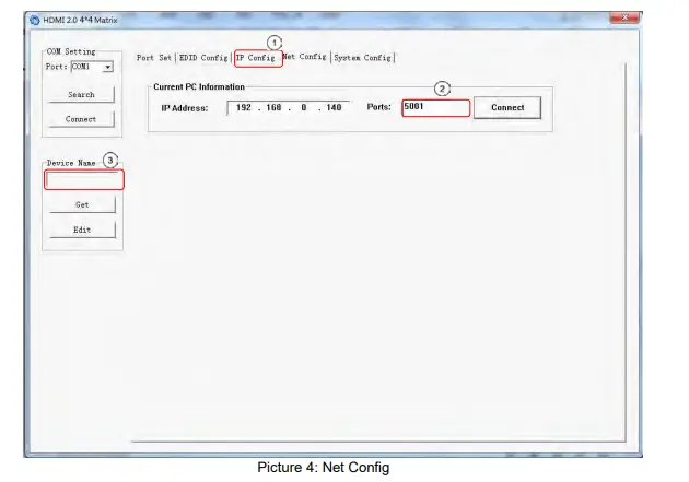
You can also click “IE” and click to enter into web.

The last tab is System Config, which allows power ON/OFF or reset, default the Matrix.

Command Control
- Open CommUart Assistant.
- Comport setting:
Baud Rate:| 115200 bps
---|---
Parity:| None
Data Bits:| 8 bit
Stop Bits:| 1 bit
NOTE :
Serial over Ethernet setting is IP port: 5000
-
Enter Port Command in Send options.

Note: All commands and responses are in ASCII. Commands and are white space
insensitive and are terminated with #. -
General Commands
Command| Function| Note
---|---|---
@W 04 00 01 02 03 #| PTP Function| Allows all outputs to be switched to the specified inputs in a single command.
@W 50 #| Reboot| Reboot matrix
@W 51 #| Restore Factory Setting| Restore unit to factory clearing any user settings
@W 0F 00 #| Standby| 00: Standby Mode
01: Cancel “Standby Mode”
-
PTP command:
Format: @W 04 O1 O2 O3 O4 #
Parameter Description:
O1 = Input number (0-3) to route to output 1
O2 = Input number (0-3) to route to output 2
O3 = Input number (0-3) to route to output 3
O4 = Input number (0-3) to route to output 4
Example: @W 04 02 02 01 00 #Route input 3 to outputs 1 and 2, input 2 to output 3, and input 1 to output 4 -
Output Routing Command:
Format: @W OO II #
Parameter Description:
OO = Output Number as indicated below:
II = Input Number as indicated below:Command| Description
---|---
00| Output1
01| Output2
02| Output3
03| Output4
04| All Output
|
00| Input1
01| Input2
02| Input3
03| Input4
Example: @W 00 03 #
Output 1 comes from Input 4
- EDID Setting Command:
Format: @W II AA BB #:
Parameter Description:
II = Input Number to configureValue| 05| 06| 07| 08
---|---|---|---|---
Input #| Input1| Input2| Input3| Input4
AA = EDID File to use as indicated below
00= 1080P
01= 4K2K_30
02=4K2K_60(YC420)
03=4K2K_60(YC444)
04=Copy from display 1
05=Copy from display 2
06=Copy from display 3
07=Copy from display 4
BB = EDID file parameters as shown in chart below:
| Bit7 | Bit6 | Bit5 | Bit4 | Bit3 | Bit2 | Bit1 | Bit0 |
|---|---|---|---|---|---|---|---|
| HDR | 48Bit | 36Bit | 30Bit | 7.1CH | 5.1CH | 2CH | 3D |
| 1 | 1 | 1 | 1 | 1 | 1 | 1 | 1 |
| 0 | 0 | 0 | 0 | 0 | 0 | 0 | 0 |
“1” = enable the function, “0” = disable the
function.
For example: 11001001: HDR, 48Bit, 7.1CH, 3D Convert Binary code “11001001” to
hexadecimal format “C9”.
Example: @W 05 03 C9 # (Note: All characters shown are in ASCII; “C9” = 43,
39) The EDID file setting of input 1 indicates:
4K2K_60(YC444)、HDR、48Bit、7.1CH、3D. Note: This field has invalid and has no
effect for any “copy from display” EDID settings
- INPUT Enable/Disable Commands:
Format: @W 36 II AA#
Parameter Description:
II = Input Number to configure00| Input1
---|---
01| Input2
02| Input3
03| Input4
AA = Enable/Disable Input
00 = Disable the INPUT 01 = Enable the INPUT
Example: @W 36 03 00# Disables Input 4
Example: @W 36 00 01# Enables Input 1
- Matrix Status Inquiry:
Format: @R YY #:
Parameter Description:
YY = Output/Input to query as indicated below:YY| Description
---|---
30| Output1
31| Output2
32| Output3
33| Output4
34| All Output
35| Input Status
Unit responds with:
@R YY II AA BB #:
Parameter Description:
YY = status being reported:
| Command | 30 | 31 | 32 | 33 | 34 | 35 |
|---|---|---|---|---|---|---|
| Description | Output1 | Output2 | Output3 | Output4 | All Outputs | Input Status |
II = Input # ( 00 = input1…03 = input4)
00= 1080P
01= 4K2K_30
02=4K2K_60(YC420)
03=4K2K_60(YC444)
04=Copy from display 1
05=Copy from display 2
06=Copy from display 3
07=Copy from display 4
BB indicates Input EDID video/audio mode (valid only for AA=00, 01, 02, 03, I
imagine)
| Bit7 | Bit6 | Bit5 | Bit4 | Bit3 | Bit2 | Bit1 | Bit0 |
|---|---|---|---|---|---|---|---|
| HDR | 48Bit | 36Bit | 30Bit | 7.1CH | 5.1CH | 2CH | 3D |
| 1 | 1 | 1 | 1 | 1 | 1 | 1 | 1 |
| 0 | 0 | 0 | 0 | 0 | 0 | 0 | 0 |
“1”: function is enabled, “0”: function is disabled, “XX”; invalid
Example Status Request:
@R 30 #: (Get Status of Output 1)
Response: @R 30 01 04 XX #
Output 1 is connected to input2, Input2 EDID is set to “copy from display 1”,
EDID video/audio data
is not valid.
AA = Selected EDID file as defined in EDID setting command above
BB = EDID file parameters as defined in EDID setting command above
Note: All “copy from display” EDID settings return XX (invalid) for this
parameter
Example 1: @R 34 #: (Get Status of All Outputs)
Response:
@R 30 00 04 XX #
@R 31 01 00 C9 #
@R 32 02 01 C9 #
@R 33 03 04 XX #
Output 1 is connected to input1, Input1 EDID is set to “copy from display 1”, EDID video/audio data is not valid.
Output 3 is connected to input3, Input3 EDID is set to “4K2K_30”, EDID
video/audio data indicates
HDR, 48bit, 7.1CH, 3D
Output 4 is connected to input4, Input4 EDID is set to “copy from display 1”, EDID video/audio data is not valid.
Example 2: @R 35 #: (Get All Input Status)
Response: @R 35 CC #:
CC = input channel signal status (HDMI and +5V present (cable connected to
source)) as described below:
| Bit7 | Bit6 | Bit5 | Bit4 | Bit3 | Bit2 | Bit1 | Bit0 |
|---|---|---|---|---|---|---|---|
| In 4 HDMI | In 3 HDMI | In 2 HDMI | In 1 HDMI | Input 4 +5V | Input 3 +5V | Input 2 | |
| +5V | In 1 +5V | ||||||
| 1 | 1 | 1 | 1 | 1 | 1 | 1 | 1 |
| 0 | 0 | 0 | 0 | 0 | 0 | 0 | 0 |
“1” signal is present, “0” signal is not present
Example Input Status Request:
@R 35 #:
Response:
@R 35 CE #
HDMI signal present on inputs 4 and 3, +5 volts present on pin 18 of inputs 4,
3, and 2.
Web GUI Control
The default IP Address of HDMI Matrix is 192.168.1.168.
Change the IP address of your PC.
- Connect the HDMI Matrix and PC to the LAN.
- Configure your PC as follows:
Click Start > Control Panel > Network and Sharing Center.
Click Change Adapter Settings.
Highlight the network adapter you want to use to connect to the device and click

Change settings of this connection.
Connect to the device and click change settings of this connection:
- Highlight Internet Protocol Version 4 (TCP/IPv4) by clicking on the item.
- Click Properties

-
Select Use the following IP Address for static IP addressing and fill in the details.
For TCP/IPv4 you can use any IP address in the range 192.168.1.2 to 192.168.1.254 (excluding
192.168.1.168).

-
Click OK.
-
Click Close.
Controlling the Matrix via the WEB GUI
Open a Web browser and enter the IP address of the HDMI Matrix:192.168.1.168, then you can set the function as shown below:


Limited Warranty
The DV-HMSW4K-44 is warranted against failures due to defective parts or faulty workmanship for a period of three years after delivery to the original owner. During this period, FSR will make any necessary repairs or replace the unit without charge for parts or labor. Shipping charges to the factory or repair station must be prepaid by the owner, return-shipping charges (via UPS Ground) will be paid by FSR.
This warranty applies only to the original owner and is not transferable. In addition, it does not apply to repairs done by other than the FSR factory or Authorized Repair Stations.
This warranty shall be cancelable by FSR at its sole discretion if the unit has been subjected to physical abuse or has been modified in any way without written authorization from FSR. FSR’s liability under this warranty is limited to repair or replacement of the defective unit.
FSR will not be responsible for incidental or consequential damages resulting from the use or misuse of its products. Some states do not allow the exclusion of incidental or consequential damages, so the above limitations may not apply to you. This warranty gives you specific legal rights, and you may also have other rights which vary from state to state.
Warranty claims should be accompanied by a copy of the original purchase invoice showing the purchase date (if a Warranty Registration Card was mailed in at the time of purchase, this is not necessary). Before returning any equipment for repair, please read the important information on service below.
SERVICE
Before returning any equipment for repair, please be sure that it is
adequately packed and
cushioned against damage in shipment, and that it is insured. We suggest that
you save the original
packaging and use it to ship the product for servicing. Also, please enclose a
note giving your
name, address, phone number and a description of the problem.
NOTE: All equipment being returned for repair must have a Return
authorization (RMA) Number.
To get a RMA Number, please call the FSR Service Department (1-800-332-FSR1).
Please display
your RMA Number prominently on the front of all packages.
CONTACT INFORMATION
Customer Support
FSR INC.
244 Bergen Blvd.
Woodland Park, NJ 07424
Phone: 973-785-4347 Order Desk Fax:
973-785-4207
E-mail: sales@fsrinc.com
Web Site: http://www.fsrinc.com
References
Read User Manual Online (PDF format)
Read User Manual Online (PDF format) >>