VISION FUTURA VF1300 Direct Fireplaces User Guide
- June 9, 2024
- VISION FUTURA
Table of Contents
VISION FUTURA VF1300 Direct Fireplaces User Guide

IMPORTANT INFORMATION – AMBIENT LIGHT KIT
This appliance can be used with an LED mood lighting kit approved by Vision Futura Fires – The Solus Ambient Light Kit (available from your retailer). Other, non-approved LED light kits must not be used as they may damage the appliance and invalidate the warranty. The Solus Ambient Light Kit must only be used when connected directly to the appliance using the pre- fitted connecting adaptor (this can be found at the bottom right-hand corner of the appliance by the mains plug, see Fig. 1a). The Solus Ambient Light Kit must not be adapted to be operated independently of the appliance, such as modifying it to run on an independent 240v supply.
The Solus Ambient Light Kit is supplied as a 3m LED strip with adhesive tape
backing, a 2m extension cable (not illuminated) and a 2-way splitter which may
be used to attach two separate kits to the same appliance, allowing each kit
to be routed to different directions/locations.

The length of an individual kit may be extended by joining another kit using LED strip connectors (not supplied), but only to a maximum of the appliance loadings, see table below for details.
| APPLIANCE | VF1300 | VF1500 | VF1800 |
|---|---|---|---|
| MAX. LENGTH OFLED STRIP ALLOWED | 3 METRES | 3 METRES | 4.5 METRES |
IMPORTANT: When fitting a Solus Ambient Light Kit into an appliance that is built into a sealed fireplace (such as a media wall), the kit must be fitted to the appliance during the initial build stage. The Solus Ambient Light Kit is not a retrofit option as the connecting adapter on the appliance is often not accessible after installation in these installation types.
Typically in such installations, the kit will be connected when the appliance is placed onto the wooden purpose built base. The appliance should then be fixed to the wall or framework at that point, ready for the remainder of the installation to be constructed around it to form the completed design. The LED strip can then be routed to its designated area, with care not to damage the strip or cable during the process. Damage can occur if the strip or cable is stretched or snagged on part of the structure/installation. If the cable is damaged at the point of the appliance, it may need to be replaced completed and this would not fall within the scope of the warranty. It is best practice to test that the Solus Ambient Light Kit is working correctly before the final boarding has been fitted to the installation. Once you are satisfied that the lighting is correctly working in accordance with the controls on the remote control, the final boarding or enclosure can take place and the installation can be finished.
When finishing the installation with a plaster, it is important to protect the appliance and ambient light kit from any water or plaster that can be spilled during that process. Plaster can be difficult to remove when dried and can damage the cable. Water must not be able to penetrate the cable or the appliance at any point during the installation build.
Before installation, check that all parts included are undamaged. If the appliance is damaged, check with the supplier before installation and operation. If the supply cord is damaged, it must be replaced by the manufacturer, its service agent or similarly qualified persons in order to avoid a hazard.
CAUTION: In order to avoid a hazard due to the inadvertent resetting of the thermalcut-out, this appliance must not be supplied through an external switching device, such as a timer, or connected to a circuit that is regularly switched on and off by the utility.
- Do not use the appliance outdoors.
- Do not use the appliance in the immediate surroundings of a bath, a shower or a swimming pool.
- Do not leave the appliance unattended during use.
- Do not run the mains cable under carpet, rugs, etc.
- Do not locate the appliance immediately below a fixed socket outlet or connection box.
- Do not install the appliance using an extension cord.
- Do not install the appliance in an open flue.
- Do not insert any objects into the appliance.
- Do not operate the appliance near flammable materials or fire.
- Do not clean the appliance with abrasive cleaners.
- Do not use this fire in rooms that have explosive gas in them (for example petrol), or if you are using solvents, glue, aerosol spray or in flammable paints, as these may catch fire.
- Do not use this appliance in small rooms when they are occupied by persons not capable of leaving the room on their own, unless constant supervision is provided.
- Do switch off and unplug the appliance from the main socket when not in use or before cleaning and maintenance.
- Do keep the appliance away at least 1 meter from furniture, curtains or other combustible material when in use.
- Do ensure the plug remains easily accessible after installation of the appliance.
- Do use this appliance on a horizontal and stable surface.
CAUTION: Some parts of this product can become very hot and cause burns. Particular attention has to be given where children and vulnerable people arepresent.
Children of less than 3 years should be kept away from the products unless continuous supervised. Children aged from 3 years and less than 8 years shall only switch on/off the appliance provided that it has been placed in its intended normal operating position and they have been given supervision or instruction concerning use of the appliance in a safe way and understand the hazards involved. Children aged from 3 years and less than 8 years shall not plug in, regulate and clean the appliance or perform user maintenance.
- NOTE: A dedicated, properly fused 13 Amp circuit is required, rated for the appropriate voltage (230-240V). An isolation switch should also be incorporated in cases where the product plug is inaccessible after installation.
- NOTE: This appliance must be earthed.
- WARNING! Construction and wiring (including electrical safe zones) must comply with local building codes and other applicable regulations to reduce the risk of fire, electric shock and injury to persons.
- WARNING! To reduce the risk of fire, electric shock or injury to persons, always use a licensed electrician.
- WARNING! Information for authorized person or service center only: A nonrewireable plug fitted with a 13A fuse is supplied. Should the fuse or plug need replacing, and you are competent to do so, it must be replaced with a 13A fuse or plug being 13A BS1363A approved.
- WARNING: In order to avoid overheating, do not cover the heater or air vents located on the appliance or obstruct the air circulation around the appliance.
WARNING! DO NOT COVER
TECHNICAL INFORMATION
| VF1300| VF1500| VF1800
---|---|---|---
Weight (kg)| See outer packaging.| See outer packaging.| See outer packaging.
Dimensions (mm)| H548x1330xD296| H548x1530xD296| H548x1830xD296
Supply Voltage| 230-240V AC/50Hz| 230-240V AC/50Hz| 230-240V AC/50Hz
Max. Power Consumption| 2000W| 2000W| 2000W
Power for Flame Effect| 45W| 48W| 58W
Power for Ambient Light Kit| 15W| 10W| 15W
HEAT OUTPUT| SYMBOL| VALUE| UNIT
---|---|---|---
Nominal Heat Output| Pnom| 1.8-2| kW
Minimum Heat Output| Pmin| 1| kW
Maximum Continuous Heat Output| Pmax| 2| kW
AUXILIARY ELECTRICITY CONSUMPTION| |
At Nominal Heat Output| elmax| 12.5| W
At Minimum Heat Output| elmin| 12| W
In Standby Mode| elSB| 1.1| W
TYPE OF HEAT OUTPUT / ROOM TEMPERATURE CONTROL| YES / NO
---|---
Single stage heat output and no room temperature control| NO
Two or more manual stages, no room temperature control| NO
With mechanic thermostat room temperature control| NO
With electronic room temperature control| YES
Electronic room temperature control plus day timer| YES
Electronic room temperature control plus week timer| YES
OTHER CONTROL OPTIONS| YES / NO
Room temperature control, with presence detection| NO
Room temperature control, with open window detection| YES
With distance control option| NO
With adaptive start control| YES
With working time limitation| NO
With black bulb sensor| NO
ITEMS| MAIN CONTROL BOARD| REMOTE CONTROL
---|---|---
Hardware| RC01-073A01-V0.0| RF4B5B-V1.0
Software/Logic| TC01-073A01-V1.0| RCS26A-V1.0
Frequency| FSK 433.92MHz| FSK 433.92MHz
Maximum Transmit Power| 0.5mW| 0.5mW


CONTENTS LIST

PART| DESCRIPTION AND QUANTITY| PART| DESCRIPTION AND
QUANTITY
---|---|---|---
1| SIDE GLASS TRIM (TOP/BOTTOM) X 4| 12| SHELF SUPPORT BRACKET (SHORT) X 2
2| SIDE GLASS TRIM (SIDE) X 2| 13(NOT SHOWN)| ORANGE GLASS SUCKER X 2
3| METAL SIDE PANEL X 2| 14(NOT SHOWN)| MAGNET TOOL X 1
4| SIDE GLASS PANEL X 2| 15(NOT SHOWN)| POWER CABLE
5| APPLIANCE X 1| 16(NOT SHOWN)| REMOTE CONTROL HANDSET X 1
6| WALL MOUNTING BRACKET X 1| 17(NOT SHOWN)| AAA BATTERY X 2
7| POWER CABLE SECURING BRACKET X 1| 18(NOT SHOWN)| ST4*8 SCREW X 19
8| MAGNETIC SIDE DECORATIVE PANEL X 2| 19(NOT SHOWN)| DECORATIVE FUEL LOGS
9| SMALL MOUTING BRACKET X 4| 20(NOT SHOWN)| BAG OF GLASS EMBERS X 1
10| FRONT GLASS PANEL X 1| 21(NOT SHOWN)| BAG OF VERMICULITE GRANULES X 1
11| SHELF SUPPORT BRACKET (LONG) X 1| 22(NOT SHOWN)| INSTRUCTION MANUAL X 1
INSTALLATION
Before installation, check that all parts are included and undamaged. If the appliance is damaged, check with the supplier before installation and operation. If the mains power supply lead is damaged in any way, it must be replaced by a suitable equivalent approved by the manufacturer.
The main box contains the appliance, 2 x suction cups and 1 x magnet tool. Packed with the appliance (behind the glass panel) are additional boxes each with a contents list printed on the outside of each box.
PREPARING THE APPLIANCE
GLASS REMOVAL – ACCESSING PARTS
To gain access to various contents required for installation follow steps
shown in Fig.1 through to Fig.4 to remove the glass panel on the front
of the appliance.

REMOVAL OF WALL MOUNTING BRACKET
The wall mounting bracket is secured to the rear panel of the appliance.
Remove the screws and the wall mounting bracket and put aside for later use –
see Fig. 5.

POWER CABLE
After inserting the power cable into the socket on the bottom right side of
the appliance, secure in place using the power cable securing bracket and
ST4*8 screw (found inside Box #1) – see Fig.6.

ASPECT TYPE
The appliance can be installed in three different aspects:
- Front (1 glass panel)
- Corner (2 glass panels)
- Panoramic (3 glass panels)
Front Aspect
Your appliance will arrive in a front aspect with metal side panels already
fitted – see Fig. 7.

Corner Aspect
For a corner aspect, choose which side you want to feature a glass panel and
remove the 7 screws that secure the metal side panel to the appliance – see
Fig. 8. Carefully remove the panel and keep the screws in a safe place.
Using the removed screws, take 2 top/bottom side glass edge trims and 1 side
side glass edge trim and screw them to the appliance as shown below – see
Fig. 9.

Panoramic Aspect
For a panoramic aspect, repeat the corner aspect procedure on the opposite
side of the appliance – see Fig. 10.

The manufacturer does not accept any liability for any injuries or damages that may occur due to improper handling or installation. Ensure that the wall upon which the appliance is to be installed and any wall fixings used are sufficiently strong enough to hold the weight of the appliance (appliance weight can be found printed on the packaging). Plasterboard alone is not considered a structural material and it is not recommended to reply solely on plasterboard fittings to support the weight of the appliance. If the appliance or any structure linked to the appliance is to be fitted to a wall with a timber frame construction, adequate wooden supporting members must be fitted using appropriate fixings. If this is not possible then steps must be taken to strengthen the wall before installation.
INSTALLATION TYPES
WALL MOUNTED
The appliance is supplied with a wall bracket which is secured to the rear of the appliance.
Step 1
Remove the bracket from the rear of the appliance, place the bracket in the
desired position ensuring it is level, mark the fixing points and use
appropriate fixings to secure to the wall.
Step 2
Attach the bottom mounting brackets to the appliance using x4 ST4 screws see
Fig 11 the appliance then can be lifted on to the wall bracket to enable the
bottom bracket fixing points to be marked on the wall. Then use suitable
fixings to secure the bottom mounting brackets to the wall.

Note See details of the weight of the appliance in the technical information to help determine the correct fixings.
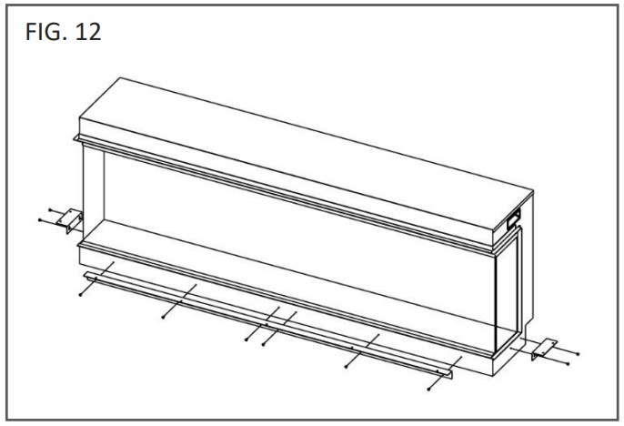
SUITE ELEMENTS
Suite elements can be fitted to the appliance using the shelf support brackets
– see Fig. 12. The brackets can be adjusted up or down to suit a range of
shelf material thicknesses from 15-24mm. Once the correct thickness has been
set, offer the shelf to the appliance in a smooth manner.
STUD/FEATURE WALL
Ensure that the stud wall has a supporting header – the weight of the finished wall should not rest on the top of the appliance. The base of the stud work must be able to take the full weight of the appliance.
The 4 small mounting brackets can be fitted to the appliance as shown in
Fig. 13 for securing to a timber frame.

FINISHING
MAGNETIC SIDE DECORATIVE PANELS
The appliance is supplied with 2 magnetic panels that can be fitted when
installing in a panoramic or corner aspect. These panels are simply positioned
against the side of the appliance, behind the side glass edge trim – see
Fig. 14.

LOG AND EMBER ARRANGEMENT
The logs can be arranged freely on the fire allowing you to create your own
unique appearance. For the best results it is recommended to position the logs
across the fuel bed first; experiment with position angles and overlapping the
logs so that some rest on each other – see. Fig. 15. Then, when you are
happy with the layout, carefully scatter the glass embers around all the logs,
ensuring that all visible areas of the fuel bed, including underneath and
behind the logs, are covered – see Fig. 16. Finally, in a similar
manner,carefully scatter the vermiculite granules over the glass embers
ensuring good coverage – see Fig. 17. Note that the quantity of logs may
differ depending on the appliance type.

OPERATION
The appliance can be operated conveniently in 2 different ways: manually or via the remote control handset.
MANUAL CONTROL

On/Off
Press to turn on power to the appliance. Button pushed in indicates power is
on, button pushed out indicates power is off.
Illumination On/Off
Press to turn on the appliance with the last used flame and fuel bed settings
without any heat. Press again to turn off the flame effect and fuel bed
illumination..
Fuel Bed Colour
Press to cycle through the 9 colour options for the fuel bed.
Flame Colour
Press to cycle through the 9 colour options for the flames.
Press and hold for 3 seconds to disable the audible ‘beep’ when buttons on the appliance or remote control handset are pressed.
REMOTE CONTROL

Ensure that 2 AAA batteries are inserted into the remote control handset. The battery power level is indicated by the column of bars to the right side of the temperature display when the appliance is in standby mode. 5 bars indicates the batteries are full, 1 bar indicates the batteries are empty and need to be replaced immediately.
Remote Control Setup
Press and hold the Illumination On/Off button on the appliance until you hear
two beeps, release the button.
Press Standby button on the remote control handset and you will hear one beep.
The remote is connected with the appliance.
Button 1: Favourite Mode
Press and hold for 3 seconds to store the current flame and fuel bed colour
settings. Press again to revert to these settings.
Button 2: Standby
Turns on the appliance with the last used settings without any heat. Places
the appliance into standby mode with all features turned off.
Button 3 &8: Minus & Plus
Use to navigate through different on-screen menus.
Button 4: Fuel Bed Colour
Repeatedly press to cycle through fuel bed colour menu. Whilst in the fuel bed
colour menu, press the plus and minus buttons to increase and decrease the
fuel bed brightness – 1 bar is the dimmest setting, 5 bars is the brightest
setting.
- On screen Fb.0 = Flame off
- On screen Fb.1 = Red
- On screen Fb.2 = Orange
- On screen Fb.3 = Yellow
- On screen Fb.4 = Green
- On screen Fb.5 = Light Blue
- On screen Fb.6 = Dark Blue
- On screen Fb.7 = Violet
- On screen Fb.8 = White
- On screen Fb.9 = Multi-colour change
Button 5: Flame Colour
Repeatedly press to cycle through flame colour menu. Whilst in the flame
colour menu, press the plus and minus buttons to increase and decrease the
flame brightness – 1 bar is the dimmest setting, 5 bars is the brightest
setting.
- On screen FL.0 = Flame off
- On screen FL.1 = Red
- On screen FL.2 = Orange
- On screen FL.3 = Yellow
- On screen FL.4 = Green
- On screen FL.5 = Light Blue
- On screen FL.6 = Dark Blue
- On screen FL.7 = Violet
- On screen FL.8 = White
- On screen FL.9 = Multi-colour change
Button 6: Settings
Press and hold for 3 seconds to enter menu for setting date and time. Press
and hold for 6 seconds to enter menu for setting 7 day programme.
Button 7: Cancel
Use when navigating through on-screen menus.
Button 9: Heater Mode
Press to cycle through the heat output options.
- press: I = Cool blow setting
- press: II = Low heat setting
- press: III = High heat setting
- press: III = Auto heat setting when weekly timer is set
Whilst in heater mode after selecting low or high heat setting, press the – and + buttons to select the temperature you want the room to reach. Note: if the room temperature is already higher than the temperature selected, the heater will not activate. To switch between ℃/℉ hold down the – and + buttons for 3 seconds.
Open Window Detection is an innovative eco feature that detects a rapid drop in room temperature caused by an open window. The warning word “OPn” will be displayed on the screen and the heater will be turned off. If the room temperature rises or the remote control is operated manually, the heater will return to its normal working state.
Button 10: Ambient Lighting (if appliance is fitted with optional Ambient Lighting Kit) Repeatedly press to turn on ambient lighting and cycle through the different colour options.
Button 11: Timer Mode
Repeatedly press to cycle through timer options. Select an amount of time for
the appliance to operate then automatically turn off. Choose between .5, 1, 2,
3, 4, 5, 6, 7, 8, 9 hours.
Button 12: Enter
Use when navigating through on-screen menus.
Button 13: Calendar
Use when navigating through the weekly timer menu.
SETTING DATE AND TIME
Press and hold the Settings button for 3 seconds to set the time and date.
Press the – button to set the hour. Press the + button to set the minute.
Press the Calendar button to set the day. Press the Enter button to save the
setting.
Note: settings will not be saved without any operation within 10 seconds.
SETTING WEEKLY TIMER
Press and hold the Settings button for 6 seconds to set the weekly timer.
Press – or + buttons to choose the time period. 5 periods can be selected.
Press the timer button to set the weekly timer start time – ‘ON’ will flash on the screen. Press – to set the hour and press + to set the minute. Press again to set the weekly timer end time – ‘OFF’ will flash on the screen. Press – to set the hour and press + to set the minute.
Press the Heater Mode button to set the desired temperature setting (from 16 28°C)
Repeatedly press the Calendar button to set the week. Press to save the week settings. Press X to cancel.
Press the Settings button to save the above setting.
CLEANING & MAINTENANCE
IMPORTANT: ALWAYS DISCONNECT THE APPLIANCE FROM THE POWER SUPPLY AND ALLOW TO COOL BEFORE CLEANING.
Any repairs or maintenance should only be carried out by a suitably qualified competent person.
The appliance should be occasionally cleaned using a dry cloth. Do not use detergents, abrasive cleaners of furniture polish.
To clean the glass, use a lightly damp cloth and ensure any moisture is dried fully using a lint free cloth.
Ensure that the heater vent is kept dust free by occasionally vacuuming the area using a brush attachment.
TROUBLESHOOTING
Resetting the Thermal Cut Out
The appliance is fitted with an Electronic Safety Control (E.S.C.). This is a safety device which switches off the fire if, for any reason, the appliance overheats, e.g. when covered. If the heater stops operating while the flame effect continues working normally, this indicates that the E.S.C. is in operation. The E.S.C. can only be reset after the appliance has cooled down and the appliance has been reset. Re-setting of the E.S.C. procedure is as follows:
- Switch off the appliance (Manual On/Off switch) and leave it off for approximately 10-15 minutes.
- Remove any obstruction to the fan heater outlet or fan blades etc. Make sure that the power supply is disconnected with the plug socket outlet while doing this.
- Switch on the appliance and the E.S.C. will be reset.
- Ensure that the appliance is functioning correctly. If the E.S. Control operates again, the appliance should be checked by a competent electrician.
| PROBLEM | POSSIBLE CAUSE | SOLUTION |
|---|---|---|
| Appliance will not turn on. | Problem with power supply. | Check that the |
appliance is plugged in to the power supply and switched on.
Check and replace fuse in the plug if necessary.
Check that the main power switch on the appliance is turnedon.
Remote control does not work.| Batteries have expired.| Replace batteries.
Remote has de-synched with appliance.| Ensure that the appliance is turned on.
Re-synch the remote by pressing the – button and the + button at the
same time and holding for 3 seconds.
No heat| Incorrect thermostat setting.| Increase the desired temperature
higher than the current room temperature.
Overheating may have engaged the E.S.C. feature.| See above for reset
procedure.
Heat turns off before desired temperature is reached.| Open window detection
has activated.| Check that any windows in the room are closed.
Electrical appliances should not be disposed as household waste. Separate collection facilities should be used in the disposal of electrical appliances. Contact your local government for information about the available collection systems. If electrical appliances are disposed of in landfills or dumps, hazardous substances can leak into the groundwater and get into the food chain, damaging your health and well-being.
This fire complies with the Safety Standards EN60335-1 and EN60335-2-30 which covers the essential requirements of the Low Voltage Directive 2014/35/EU and the EMC standards EN55014-1; EN55014 2; EN61000-3-2 and EN61000-3-3 which covers the essential requirements of the European Electro Magnetic Compatibility 2014/30/EU, and the RED standards EN300220-2, EN30148 9-1, EN301489-3 and EN6247 which covers the essential requirements of the European Radio Equipment Directive 2014/53/EU.
This fire complies with the Safety Standards BS60335-1 and BS60335-2-30 which covers the essential requirements of the Electrical Equipment (Safety) Regulations 2016 (S.I.2016/1101) and the EMC standards BS55014-1; BS 55014-2; BS61000-3-2 and BS61000-3-3 which covers the essential requirements of the Electro Magnetic Compatibility Regulations 2016 (S.I.2016/1091).and the RED standards BS300220-2, BS301489-1, BS301489-3 and BS6247 which covers the essential requirements of the European Radio Equipment Regulations 2017.

Read User Manual Online (PDF format)
Read User Manual Online (PDF format) >>