Minostone MR40Z S2 Remote Control Switch Instruction Manual
- June 6, 2024
- Minostone
Table of Contents
Minostone MR40Z S2 Remote Control Switch Instruction Manual
S2 Remote Control Switch


Specifiction
- Battery: CR2032*1
- Frequency: 908.42MHz
- Temperature Range: 32°F~104°F
- Indoor use in dry location

- Please read this the online guidels at support Minosto.com/Z-wave remote carefully
- Do not use it in location with direct water contact.
- Contains small parts keep away from children.
Power the device
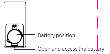 Use by hand open the remote cap, and push in to separate the 2 halves
- Remove the battery tabs
- Your Z-wave remove Immediately should flash LED to indicate it is powered.
S2 Remote Control Switch features
- Power by battery,no need wires needed.Note the ± direction of the battery
- Control other Z-wave devices and enable scenes with a click of a button
- The device with S2 and SmartStart support
Please contact us if you have any questions:
ask@minoston.com
www.minoston.com
Z-wave Control
Adding Device To your hub and Z-Wave Network for QR code
 Inclusion/Exclusion Function
To add the device
- Follow the instructions for your Z-Wave certified controller to adding device from the Z-Wave network.
- Once the controller is preparing to add your device, press the FIRST BUTTON(ONLY) 5 times, LED flashing in blue during inclusion and LED stays on green for 2 seconds after inclusion successfully. If LED flashing purple for 3 seconds, please reset the device. LED will stay on red for 2 seconds after inclusion failed.
To remove the device
- Follow the instructions for your Z-Wave certified controller to remove a device from the Z-Wave network.
- Once the controller is preparing to remove your device, press the SECOND BUTTON(ONLY) 5 times, LED flashing in purple during exclusion and the LED stays on green for 2 seconds after exclusion successfully. LED will stay red for 2 seconds after exclusion failed.
Wake up the Device
Press the THIRD buttom 5 times quickly, LED will stay solid on blue when awake and will turn off when device goes back to sleep mode.
Factory Reset
Manual: Press the Fourth button 5 times, LED flashing red 5S while press 5 times again, LED will stays red for 2 seconds then off.
Note: Install the custom device handler to access the right functions if you’re using the SmartThings hub. Please visit our website: www.minoston.com or email us: ask@minoston.com.
Configuration Parameter
- Parameter 1 Battery report threshold % Use it to set battery level for battery reports. size=1 byte Available range : 1-20 (DEFAULT): 10%
- Parameter 2 Low Battery alarm report Use it to set battery level for low battery reports. size=1 byte Available range : 5%-20% (DEFAULT) : 5%
- Parameter 3 LED Indicator Color for First button remote control (Scene 1 activation) Choose the LED indicator color for First button remote control triggers size=1 byte Available settings: 0–6
- Value=0 White
- Value=1 Purple
- Value=2 Orange
- Value=3 Cyan
- Value=4 Red
- Value=5 Green
- Value=6 Blue
- (DEFAULT) : 0
- Parameter 4 LED Indicator Color for Second button remote control (Scene 2 activation) Choose the LED indicator color for Second button remote control triggers size=1 byte Available settings: 0–6
- Value=0 White
- Value=1 Purple
- Value=2 Orange
- Value=3 Cyan
- Value=4 Red
- Value=5 Green
- Value=6 Blue
- (DEFAULT) : 1
- Parameter 5 LED Indicator Color for Third button remote control (Scene 3 activation) Choose the LED indicator color for Thrid button remote control triggers size=1 byte Available settings: 0–6
- Value=0 White
- Value=1 Purple
- Value=2 Orange
- Value=3 Cyan
- Value=4 Red
- Value=5 Green
- Value=6 Blue
- (DEFAULT) : 2
- Parameter 6 LED Indicator Color for Fourth button remote control (Scene 4 activation) Choose the LED indicator color for Fourth button remote control triggers size=1 byte Available settings: 0–6
- Value=0 White
- Value=1 Purple
- Value=2 Orange
- Value=3 Cyan
- Value=4 Red
- Value=5 Green
- Value=6 Blue
- (DEFAULT) : 3
- Parameter 7 LED Indicator Brightness Choose the LED indicator Brightness level size=1 byte Available settings: 0–10
- Value=0 LED off
- Value=1 10% Brightness
- Value=2 20% Brightness
- Value=3 30% Brightness
- Value=4 40% Brightness
- Value=5 50% Brightness
- Value=6 60% Brightness
- Value=7 70% Brightness
- Value=8 80% Brightness
- Value=9 90% Brightness
- Value=10 100% Brightness
- (DEFAULT) : 5
Scene Control
This remote supports four scene controls
- Scene 1 : First Button 1-Tap/2-Tap/3-Tap/Held/Released
- Scene 2 : Second Button 1-Tap/2-Tap/3-Tap/Held/Released
- Scene 3 : Third Button 1-Tap/2-Tap/3-Tap/Held/Released
- Scene 4 : Fourth Button 1-Tap/2-Tap/3-Tap/Held/Released
Association Group
This remote supports 9 Association Group controls Support group number: 9 Each group max. Support 10 devices
- Group 1 Lifeline
- Group 2 First button press 1x send basic set 0xff, Second button press 1x send basic set 0x00.
- Group 3 Third button press 1x send basic set 0xff, Fourth button press 1x send basic set 0x00
- Group 4 First button hold more than 0.5s send SWITCHMULTILEVEL
- START_LEVEL_CHANGE(Dim Up)
- First button release send SWITCH_MULTILEVEL_STOP_LEVEL_CHANGE
- Second button hold more than 0.5s send SWITCHMULTILEVEL
- START_LEVEL_CHANGE(Dim Down)
- Second button release send SWITCH_MULTILEVEL_STOP_LEVEL_CHANGE
- Group 5 Third button hold more than 0.5s send SWITCHMULTILEVEL
- START_LEVEL_CHANGE(Dim Up)
- Third button release send SWITCH_MULTILEVEL_STOP_LEVEL_CHANGE
- Fourth button hold more than 0.5s send SWITCHMULTILEVEL
- START_LEVEL_CHANGE(Dim Down)
- Fourth button release send SWITCH_MULTILEVEL_STOP_LEVEL_CHANGE
- Group 6 First button press 1x to toggle on/off (send basic set 0xff or 0x00).
- Group 7 Second button press 1x to toggle on/off (send basic set 0xff or 0x00).
- Group 8 Third button press 1x to toggle on/off (send basic set 0xff or 0x00).
- Group 9 Fourth button press 1x to toggle on/off (send basic set 0xff or 0x00).
Command Class
Generic Device Class: 0x07 – GENERIC_TYPE_SENSOR_NOTIFICATION
Specific Device Class: 0x01 – SPECIFIC_TYPE_NOTIFICATION_SENSOR
Command Classes:
- 0x5E – COMMAND_CLASS_ZWAVEPLUS_INFO
- 0x85 – COMMAND_CLASS_ASSOCIATION
- 0x8E – COMMAND_CLASS_MULTI_CHANNEL_ASSOCIATION
- 0x59 – COMMAND_CLASS_ASSOCIATION_GRP_INFO
- 0x31 – COMMAND_CLASS_SENSOR_MULTILEVEL
- 0x55 – COMMAND_CLASS_TRANSPORT_SERVICE
- 0x86 – COMMAND_CLASS_VERSION
- 0x72 – COMMAND_CLASS_MANUFACTURER_SPECIFIC
- 0x5A – COMMAND_CLASS_DEVICE_RESET_LOCALLY
- 0x73 – COMMAND_CLASS_POWERLEVEL
- 0x80 – COMMAND_CLASS_BATTERY
- 0x9F – COMMAND_CLASS_SECURITY_2
- 0x71 – COMMAND_CLASS_NOTIFICATION
- 0x87 – COMMAND_CLASS_INDICATOR
- 0x30 – COMMAND_CLASS_SENSOR_BINARY
- 0x70 – COMMAND_CLASS_CONFIGURATION
- 0x84 – COMMAND_CLASS_WAKE_UP
- 0x6C – COMMAND_CLASS_SUPERVISION
- 0x7A – COMMAND_CLASS_FIRMWARE_UPDATE_MD
Warranty
Our Products warrants this product to be free from manufacturing defects
for a period of one year from the original date of consumer purchase. This
warranty is limited to the repair or replacement of this product only and does
not extend to consequential or incidental damage to other products that may be
used with this product. This warranty is in lieu of all other warranties,
expressed or implied. Some states do not allow limitations on how long an
implied warranty lasts or permit the exclusion or limitation of incidental or
consequential damage, so the above limitations may not apply to you. This
warranty gives you specific rights, and you may also have other rights which
vary from state to state.
FCC / IC
This device complies with part 15 of the FCC and Industry Canada license-
exempt RSS standard(s). Operation is subjected to the following two
conditions: (1) this device may not cause harmful interference, and (2) this
device must accept any interference received, including interference that may
cause undesired operation.
FCC NOTE
The manufacturer is not responsible for any radio or TV interference caused by
unauthorized modifications to this equipment. Such modifications could void
the user’s authority to operate the equipment
- Reorient or relocate the receiving antenna.
- Increase the separation between the equipment and receiver.
- Connect the equipment into an outlet on a circuit different from that to which the receiver is connected.
- Consult the dealer or an experienced radio/TV technician for help.
NOTE: This equipment has been tested and found to comply with the limits for a Class B digital device, pursuant to Part 15 of the FCC Rules. These limits are designed to provide reasonable protection against harmful interference in a residential installation. This equipment generates, uses and can radiate radio frequency energy and, if not installed and used in accordance with the instructions may cause harmful interference to radio communications. However, there is no guarantee that interference will not occur in a particular installation. If this equipment does cause harmful interference to radio or television reception, which can be determined by turning the equipment off and on, the user is encouraged to try to correct the interference by one or more of the following measures
Important Note: To comply with the FCC RF exposure compliance requirements, no change to the antenna or the device is permitted. Any change to the antenna or the device could result in the device exceeding the RF exposure requirements and void user’s authority to operate the device.
Read User Manual Online (PDF format)
Read User Manual Online (PDF format) >>