Tse E4000-13-01 Docking Station for Vehicle External Diagnostic Equipment User Manual
- June 5, 2024
- Tse
Table of Contents
Tse E4000-13-01 Docking Station for Vehicle External Diagnostic
Equipment
What is a docking station for vehicle external diagnostic equipment?
Objective
- Extract 12V from USB PD Charger Supply power to external diagnostic equipment
- Converting the Ethernet pin of the OBD connector to an RJ-45 connector Convert the Ethernet pin of the OBD connector to an RJ45 connector and use a LAN cable to connect the external diagnostic equipment to the PC.
supplement
A vehicle external diagnostic device is a device that uses external tools to
diagnose the health of a vehicle. external tools to diagnose the health of the
vehicle.
How to use

Specifications
Test Standers
|
Standard
| Operation range
---|---|---
MIN| TYP| MAX
USB Type-C input| USB PD3.0 DC12V/2.5A DC15V/2A| –| –| –
LAN connector standard| RJ-45| –| –| –
OBD Connector Standard| SAE J1962| –| –| –
OBD+B Output Voltage| | 11.5V| 12V| 12.5V
OBD+B Output Current| | –| 1.2A| 2A
Operating atmosphere range| | 0℃| 25℃| 45℃
Storage temperature range| | -25℃| 25℃| 60℃
Operating humidity range| | 10%Rh| –| 90%Rh
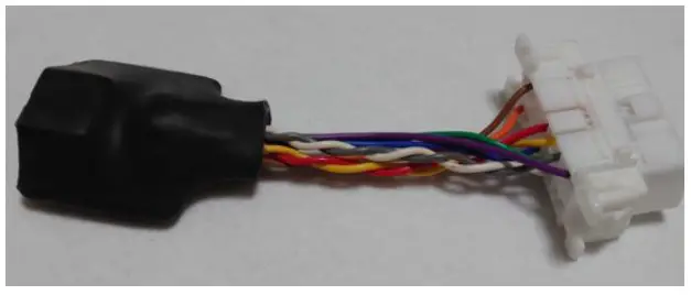
Appearance
Case discontinued due to specification change
Protected by shrink tube external dimensions (not including protruding part of
- OBD connector): W60 x H30 x D50
- OBD connector: POM (white)

actual photo
- No protective shrink tubing

- Protective shrink tubing available
Wiring diagram for use

Configuration under test
Test
Test Standards
|
Standard
---|---
FCC Subpart 15| 47 CFR 15 Subpart B ※1
EN55032| Class A
Internal frequency 108MHz or less
EN55035
| IEC 61000-4-2
IEC 61000-4-3 IEC61000-4-6
All Performance Standard C
FCC STATEMENT
This product falls under the category of digital devices used only as electronic control systems and power systems in industrial plants and is exempt from the requirements. However, conformity tests will be conducted to confirm safety.
CAUTION
Changes or modifications not expressly approved by the party responsible for
compliance could void the user’s authority to operate the equipment.
Note:
This equipment has been tested and found to comply with the limits for a Class
B digital device, pursuant to part 15 of the FCC Rules. These limits are
designed to provide reasonable protection against harmful interference in a
residential installation. This equipment generates, uses, and can radiate
radio frequency energy and, if not installed and used in accordance with the
instructions, may cause harmful interference to radio communications. However,
there is no guarantee that interference will not occur in a particular
installation. If this equipment does cause harmful interference to radio or
television reception, which can be determined by turning the equipment off and
on, the user is encouraged to try to correct the interference by one or more
of the following measures:
- Reorient or relocate the receiving antenna.
- Increase the separation between the equipment and receiver.
- Connect the equipment into an outlet on a circuit different from that to which the receiver is connected.
- Consult the dealer or an experienced radio/TV technician for help.
Passing Criteria Operation check after the test

Test Standards
|
How to check
|
eligibility criteria
---|---|---
Ethernet cabling
|
Measure the resistance of pin 3 of the OBD connector terminal and pin 1 of the RJ45 terminal.
| No more than ±5% change in resistance value after the test compared to before the
test
Measure the resistance of the 11-pin OBD connector
terminal and the 2-pin RJ45 terminal
| No more than ±5% change in resistance value after the test compared to before the
test
Measure the resistance of the 12-pin OBD connector terminal and the 3-pin RJ45 terminal
| No more than ±5% change in resistance value after the test compared to before the
test
Measure the resistance of the 13-pin OBD connector terminal and the 6-pin RJ45 terminal
| No more than ±5% change in resistance value after the test compared to before the
test
OBD
| USB Type-C| No more than ±5% change in voltage after the test compared to before the test (Standard 12V)
Read User Manual Online (PDF format)
Read User Manual Online (PDF format) >>