Winstel Controls B-VCD18SA-1 Hyper Heat Air Handler User Guide
- June 1, 2024
- Winstel Controls
Table of Contents
Winstel Controls B-VCD18SA-1 Hyper Heat Air Handler
Product Specifications
- Extreme performance
- Capacity: 1.5 to 5 Tons
- Six models available ranging from 18,000 to 60,000 BTUH
- Wired programmable control Warranty: 10 years on compressor, 10 years on parts (Some
limitations apply; see printed warranty for details)
Multi-Position Air Handler
- Power supply: 208/230V, 1 Phase, 60Hz
- Rated Capacity Range: Varies based on model
- Cooling Input Power Rated Current
- EER2, SEER2, COP, HSPF4, HSPF5
- Indoor air flow (Hi/Mi/Lo): Varies based on model
- Indoor noise level (Hi/Mi/Lo): Varies based on model
- Net/Gross weight: Varies based on model
- Refrigerant piping: Liquid side/ Gas side – 3/8″ / 3/4″
- Drainage water pipe diameter: Varies based on model
- Wireless remote controller: Standard
- Thermostat type: Wired Controller, Programmable wired Controller
Installation
- Ensure proper power supply and voltage requirements are met.
- Install the air handler in a suitable location as per the manufacturer’s guidelines.
- Connect the refrigerant piping and drainage water pipe as instructed.
Enjoy the ultimate in comfort and efficiency with the VCD-Series cold-climate
air source heat pump. With an inverter-driven compressor, the VCD-system fully
modulates to use the least amount of energy possible to maintain temperature,
while at
the same time optimizing sound levels and comfort. Hyper heat performance down
to -22°F (-30°C) means the heat pump has world-class operating parameters in
all weather conditions-and the optional electric auxiliary heat kits provide
further peace of mind.
FEATURES
-
Aluminum-alloy traditional fin-and-tube coil construction for maximum durability and corrosion resistance
-
Efficient and quiet ECM blower motor
-
Accepts traditional 24VAC thermostats for convenience and advanced control options
-
Wired programmable control included
-
Optional electric resistance heat kits (up to 25kW) provides auxiliary heat source for comfort during the worst conditions
-
Beautiful and durable gloss enameled-steel construction with insulated construction provides less than 2% cabinet leakage
-
Built-in return filter rack:
18K & 24K=16”x 20”x 1”
30-48K= 20”x 20”x 1” 60K= 24”x 20”x 1” -
Multi-position air handler

EXTREME PERFORMANCE COLD WEATHER HEAT PUMP

1.5 to 5 Tons
Six models to choose from 18,000 to 60,000 BTUH
MULTI-POSITION AIR HANDLER
Ducted Units
FEATURES| B-VCD18SA-1| B-VCD24SA-1| B-VCD30SA-1| B-VCD36SA-1| B-VCD48SA-1| B-VCD60SA-1
Power supply
| Rated| V, Ph, Hz| 208/230, 1, 60| 208/230, 1, 60| 208/230, 1, 60|
208/230, 1, 60| 208/230, 1, 60| 208/230, 1, 60
Voltage range| V| 187-253| 187-253| 187-253| 187-253| 187-253|
187-253
Cooling
| Rated Capacity (range)| ****
Btu/h
| 18,000 (6,880~21,000)| 24,000 (6,400~27,000)| 30,000 (10,000~33,600)|
36,000 (13,000~47,400)| 47,000 (15,000~48,000)| 55,000 (14,000~56,000)
Input power| W| 1,450| 2,050| 3,060| 3,673| 5,731| 6,280
Rated current| A| 6.4| 9.10| 13.20| 15.97| 24.95| 27.40
EER2| Btu/w| 12.4| 11.7| 10.00| 10.00| 8.2| 8.8
SEER2| Btu/w| 18| 17.4| 16.2| 16| 15.6| 15.3
Heating at 47°
| Rated Capacity (range)| ****
Btu/h
| 19,000 (2,800~21,000)| 24,000 (10,100~31,000)| 33,000 (11,500~37,000)|
40,000 (11,000~57,200)| 50,000 (11,000~55,000)| 55,000 (13,400~69,000)
Input power| W| 1,530| 2,100| 2,930| 3,448| 4,652| 5,060
Rated current| A| 6.8| 9.30| 13.30| 15.00| 21.20| 22.00
COP| W/W| 3.64| 3.35| 3.30| 3.36| 3.15| 3.42
HSPF4 2| Btu/w| 9.3| 10.00| 8.9| 9.5| 9.4| 9.4
HSPF5| Btu/w| 7.6| 8.00| 7.00| 7.80| 7.70| 7.6
Heating at 5° (-15°)| Capacity| Btu/h| 16,500| 24,130| 28,550|
38,890| 47,060| 51,981
COP| W/W| 2.04| 1.91| 1.77| 1.97| 1.90| 1.91
The Rated Input Current of The Power Conversion Equipment| A| 2.5|
3.0| 3.5| 3.5| 3.5| 3.5
MINIMUM CIRCUIT AMPACITY
(Indoor unit)
| A| 2.5| 4.0| 4.5| 5.0| 7.5| 9.0
MAX. FUSE (Indoor unit)| A| 15| 15| 15| 15| 15| 15
Indoor air flow (Hi/Mi/Lo)| CFM| 618/530/450| 624/695/630|
1,089/806/712| 1,189/971/865| 1,471/1,095/906| 1,806/1,359/1,136
Indoor noise level (Hi/Mi/Lo)| dB(A)| 34/31/30| 39/36/33|
42/40.5/36.5| 45/43/41| 50/47/43.5| 51/45.5/41.5
Indoor unit
| Dimension (W×D×H)| inch| 21.02×17.52×45| 21.02×17.52×45.00|
21.02×21.02×49.02| 21.02×21.02×49.02| 21.02×21.02×49.02| 21.02×24.49×52.99
Packing (W×D×H)| inch| 25.20×20.87×50.39| 25.20×20.87×50.39|
25.20×24.41×54.33| 25.20×24.41×54.33| 25.20×24.41×54.33| 27.95×26.77×56.60
Net/Gross weight| lbs.| 105.82/129.41| 105.60/127.43|
129.19/155.64| 129.19/155.64| 130.51/156.31| 162.70/190.70
Refrigerant piping| Liquid side/ Gas side| inch| 3/8” / 3/4”|
3/8” / 3/4”| 3/8” / 3/4”| 3/8” / 3/4”| 3/8” / 3/4”| 3/8 x 7/8
Drainage water pipe diameter| inch| 3/4| 3/4| 3/4| 3/4| 3/4| 3/4
Thermostat type
| Wireless remote controller| Standard| Standard| Standard|
Standard| Standard| Standard
Wired Controller| n/a| n/a| n/a| n/a| n/a| n/a
Programmable wired Controller| Standard| Standard| Standard|
Standard| Standard| Standard
Auxiliary Heat Kits
| Power of Electric Heater| Number of Circuits| ****
Voltage
| Circuit 1 MCA| Circuit 2 MCA| Circuit 3 MCA| Circuit 1 Max. Fuse| Circuit 2 Max. Fuse| Circuit 3 Max. Fuse
Optional Electric Heater
| ECD3KW| 1| 208/230V| 14A/16A| –| –| –| –| –
ECD5KW| 1| 208/230V| 23A/27A| –| –| –| –| –
ECD8KW| 1| 208/230V| 37A/42A| –| –| 40A/45A| –| –
ECD10KW| 1| 208/230V| 46A/53A| –| –| 50A/60A| –| –
ECD15KW| 2| 208/230V| 23A/27A| 46A/53A| –| 25A/30A| 50A/60A| –
ECD20KW| 2| 208/230V| 46A/53A| 46A/53A| –| 50A/60A| 50A/60A| –
ECD25KW| 3| 208/230V| 23A/27A| 46A/53A| 46A/53A| 25A/30A| 50A/60A| 50A/60A

(unit: mm/inch)
| Model (Btu/h) | W | D | T |
|---|---|---|---|
| mm | inch | mm | inch |
| 18K | 406.4 | 16 | 508 |
| 24K | 406.4 | 16 | 508 |
| 30 &36K | 495.3 | 19-1/2 | 508 |
| 48 &60K | 584.2 | 23 | 508 |
Dimensional Data
| Model (Btu/h) Dimensions | 18K | 24K | 30K~48K | 60K |
|---|
Length of A
| mm| 1,143| 1,143| 1,245| 1,346
inch| 45| 45| 49| 53
Length of B
| mm| 533| 533| 533| 533
inch| 21| 21| 21| 21
Length of C
| mm| 445| 445| 534| 622
inch| 17-1/2| 17-1/2| 21-1/50| 24-1/2
Length of D
| mm| 400| 400| 490| 580
inch| 15-3/4| 15-3/4| 19-5/16| 22-27-32
Length of E
| mm| 260| 260| 260| 260
inch| 10-1/4| 10-1/4| 10-1/4| 10-1/4
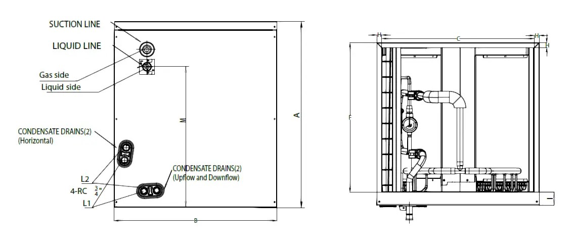
DIMENSIONAL DRAWINGS

Vertical installations
Horizontal Installations 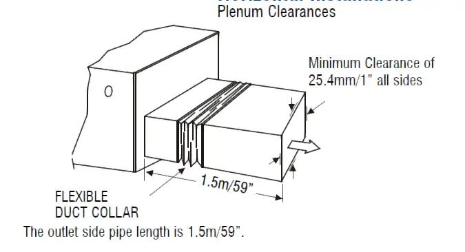
Model| MCD(18,24)B1A| MCD(30,36)B1A| MCD(30,36,48)C1A|
MCD60D1A
---|---|---|---|---
Dimensions| in.| mm.| in.| mm.| in.| mm.|
in.| mm.
A| Model Height| 18| 457| 23-1/2| 599| 24| 609| 28| 711
B| Model Width| 17-1/2| 445| 17-1/2| 445| 21| 533| 24-1/2| 622
C| Supply Air Opening Width| 16-3/16| 411| 16-3/16| 411| 19-3/4| 502| 23-1/4|
591
D| Return Air Opening Width| 15-1/8| 384| 15-1/8| 384| 19-1/2| 496| 23| 585
E| Model Depth| 21| 533| 21| 533| 21| 533| 21| 533
F| Supply Air Opening Depth| 18-5/8| 473| 18-5/8| 473| 18-5/8| 473| 18-5/8|
473
G| Return Air Opening Depth| 18| 458| 18| 458| 18-1/2| 470| 18-1/2| 470
H| Supply Air Opening Side Clearance| 5/8| 16| 5/8| 16| 5/8| 16| 5/8| 16
I| Supply Air Opening Front Clearance| 1-3/4| 45| 1-3/4| 45| 1-3/4| 45| 1-3/4|
45
J| Return Air Opening Side Clearance| 1-3/16| 30| 1-3/16| 30| 3/4| 19| 3/4| 19
K| Return Air Opening Front Clearance| 1-13/16| 46| 1-13/16| 46| 1-13/16| 46|
1-13/16| 46
L| Condensate Drains Height| 1-7/16| 37| 1-7/16| 37| 2-1/8| 54| 2-1/8| 54
M| Liquid Line Height| 10-7/8| 276| 16-1/2| 418| 16-5/16| 414| 20-1/4| 514
NOTE: AHRI combinations with MCD-Series Coils and VCD systems are “coil-only” matches, and result in low er SEER2, EER2, and HSPF2 ratings than with matchi g air handler. Review latest match information on www.marsdeliversratings.com before installation.

OUTDOOR UNIT
FEATURES
| ****
A-VCD18SA-1
| ****
A-VCD24SA-1
| ****
A-VCD30SA-1
| ****
A-VCD36SA-1
| ****
A-VCD48SA-1
| ****
A-VCD60SA-1
---|---|---|---|---|---|---
Power Supply| 208/230V,1Ph,60Hz| 208/230V,1Ph,60Hz| 208/230V,1Ph,60Hz|
208/230V,1Ph,60Hz| 208/230V,1Ph,60Hz| 208/230V,1Ph,60Hz
Cooling Capacity (BTUH)| 18,000| 24,000| 30,000| 36,000| 47,000| 55,000
SEER2| 18.0| 17.4| 16.2| 16| 15.6| 15.3
EER2| 12.4| 11.7| 10.0| 10.0| 8.2| 8.8
HSPF4 2| 9.3| 10| 8.9| 9.5| 9.4| 9.4
COP| 3.64| 3.35| 3.30| 3.36| 3.15| 3.42
Cooling Amps| 6.4| 9.10| 13.20| 15.97| 24.95| 27.40
Heating Cap. (BTUH) @ 47°F| 19,000| 24,000| 33,000| 40,000| 50,000|
59,000
Heating Amps| 6.8| 9.30| 13.30| 15.0| 21.20| 22.0
Outdoor DBA| 57| 62| 60.5| 64| 64| 63.5
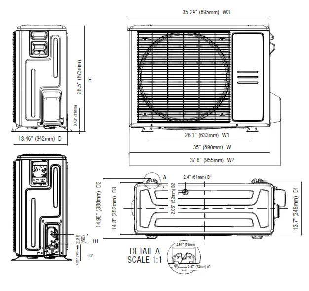
OUTDOOR UNIT DIMENSIONS
Width (inches)| 35.04| 37.24| 37.24| 37.48| 37.48| 37.48
Height (inches)| 26.50| 31.89| 31.89| 52.48| 52.48| 52.48
Depth (inches)| 13.46| 16.14| 16.14| 16.34| 16.34| 16.34
Net Wt/Shipping Wt (lbs.)| 102.95/109.79| 136.69/145.50| 159.83/169.75|
227.07/255.70| 220.24/248.90| 239.86/271.61
ELECTRICAL DATA OUTDOOR UNIT ‡
Main Power Connection| Outdoor Unit 208/230-1-60
Min. Circuit Ampacity| 16.0| 20.5| 23| 30| 40| 40
Max. Fuse/HACR Circuit Breaker| 20.0| 35| 35| 50| 50| 50
Indoor/Outdoor Connecting Cable Type| 14AWG / 4 conductor 600V THHN
unshielded stranded bare copper
LINE SETS O.D. (inch)
Line Sets O.D. (inch) *| 3/8 x 3/4| 3/8 x 3/4| 3/8 x 3/4| 3/8 x 3/4|
3/8 x 3/4| 3/8 x 7/8
Max. Line Set Length 1| 98.4| 164| 213| 213| 213| 213
Max. Elevation (outdoor) 2| 65.6| 82| 98| 98| 98| 98
Note:
*For alternative line set sizes, please refer to the VCD Vapor Line Sizing Chart
‡ Always follow local, state and national electrical codes
- Min. 10 ft. line set recommended
- Oil traps should be installed every 16.5 to 23 feet (5-7m) when the outdoor unit is installed above the indoor unit
**Verify Rating Plate Information
Prior to Installation.
Minimum Circuit Ampacity and Maximum Fuse Values May Have Changed from
Original Specifications.
Outdoor Unit Dimensions 18K
DIMENSIONAL DRAWINGS
Outdoor Unit Dimensions – 24K & 30K

Outdoor Unit Dimensions – 36K – 60K

Due to ongoing product improvements, specifications and dimensions are subject
to change and correction without notice or incurring obligations. Determining
the application and suitability for use of any product is the responsibility
of the installer.
Additionally, the installer is responsible for verifying dimensional data on
the actual product prior to beginning any installation preparations.
Third party incentive and rebate programs have precise requirements as to
product performance and certification.
All products meet applicable regulations in effect on date of manufacture;
however, certifications are not necessarily granted for the life of a product.
Therefore, it is the responsibility of the applicant to determine whether a
specific model qualifies for these incentive/rebate programs.
“This product complies with all California product labeling laws including, but not limited to, the Safe Drinking Water and Toxic Enforcement Act of 1986, more commonly known as Proposition 65.”
References
Read User Manual Online (PDF format)
Read User Manual Online (PDF format) >>