The Building Agency MX Ali Clad Max Installation Guide
- May 15, 2024
- The Building Agency
Table of Contents
- The Building Agency MX Ali Clad Max
- Product Specifications
- Product Usage Instructions
- Installation Guide
- Introduction
- Compliance
- Important Documents
- Skills Required
- Framing and Support Structures
- Storage and Handling
- Rigid Air Barriers and Wall Underlay
- Cavity Construction Options
- Window Installation Considerations
- Equipment Required
- Construction Sequence
- Installation Considerations
- Typical Layout
- AliClad Max Components
- Fixing the System
- INSTALLATION GUIDE
- Board Terminations
- Internal Corners
- Simplified Typical Detail
- References
- Read User Manual Online (PDF format)
- Download This Manual (PDF format)
The Building Agency MX Ali Clad Max
Product Specifications
- Product Name: AliClad Max Premium Aluminium Vertical Weatherboard Cladding System
- Designed by: The Building Agency
- Application: Large-scale commercial projects with a residential application
- Features: Contemporary design, available in multiple colors and finishes, engineered for durability and performance
- Compliance: Meets or exceeds New Zealand Building Code requirements
- Testing: ISO 5660.1 2015, BS8414-2:2015+A1:2015 BR135
Product Usage Instructions
-
Preparation and Skills Required
Before starting the installation process, ensure you have the necessary skills and tools required for the job. Familiarize yourself with the installation guide and ensure compliance with all relevant building codes -
Framing and Support Structures
Proper framing and support structures are essential for the installation of the AliClad Max system. Ensure that the substrate is stable, level, and able to support the cladding system. -
Storage and Handling
Store the AliClad Max components in a dry, covered area to prevent damage. Handle the components with care to avoid any dents or scratches that may affect the final finish. -
Rigid Air Barriers and Wall Underlays
Install rigid air barriers and wall underlays as per the manufacturer’s instructions to provide additional protection against external moisture and enhance the system’s durability. -
Cavity Construction Options
Consider different cavity construction options based on the specific requirements of your project. Consult the installation guide for recommended cavity sizes and configurations.
Frequently Asked Questions (FAQ)
-
Q: Can AliClad Max be painted?
A: AliClad Max comes in a variety of colors and finishes, eliminating the need for painting. However, if necessary, it can be painted using suitable exterior-grade paint. -
Q: Is AliClad Max suitable for residential applications?
A: Yes, AliClad Max is designed for large-scale commercial projects but is also suitable for residential applications, providing a durable and elegant finish.
THE BUILDING AGENCY – ALICLAD MAX INSTALLATION GUIDE
Installation Guide
PREMIUM ALUMINIUM VERTICAL WEATHERBOARD CLADDING SYSTEM
Introduction
- Performance and aesthetics combine in a contemporary aluminium cladding system. Designed in New Zealand for local conditions.
- Our tough climate calls for exterior products that can perform in all weather conditions, meet the most stringent code and standards, and bring elegance and architectural integrity. Available in a multitude of colours, finishes and even woodgrain.
- AliClad Max, designed by The Building Agency, is a premium aluminium weatherboard system that has had every detail and feature designed, tuned and resolved. Backed by decades of local experience and international product knowledge, AliClad Max offers architects, builders and developers a robust and beautifully finished product, supported on an easy-to-install fixing system engineered to perform.
- Designed for large-scale commercial projects with a residential application.
Compliance
When designed and installed in accordance with the Installation, Design and
the Specification Guide,
www.thebuildingagency.co.nz/product.
AliClad Max weatherboards will meet or exceed the requirements of the
following clauses of the New Zealand Building Code (NZBC):
- Clause B1 – Structure
- B1.3.1, B1.3.2, and B1.3.4
- Clause B2 – Durability
- B2.1, B2.2 and B2.3
- Clause E2 – External Moisture
- E2.3.2, E2.3.5, E2.3.7
- Clause C1-6: Protection from Fire
- C3 : Fire effecting areas beyond the Fire Service C3.5, C3.6 and C3.7.
- The AliClad Max cladding system meets the requirements of ISO 5660.1 2015 (AWTA 22-000683 & AWTA 22-000683 Group number assessment) for Type A.
- The AliClad Max Cladding System has been tested to BS8414-2:2015+A1:2015 BR135 (refer BRANZ FF13923-02-1).
Important Documents
Refer to the following The Building Agency documents:
-
ALICLAD MAX Product Technical Statement.
-
ALICLAD MAX Design Guide.
-
ALICLAD MAX Installation Guide.
-
ALICLAD MAX PASS No 19233.
-
ALICLAD MAX Specification Guide.
-
ALICLAD MAX Care & Maintenance Guide.
Skills Required
AliClad Max must be installed by a Building Agency Ltd certified/approved installer or Licensed Building Practitioner (LBP).
Installation Considerations
- It is the responsibility of the installer to ensure that the AliClad Max Cladding System is appropriate for the intended application.
- Consideration should be given to shrinkage of framing and Thermal expansion at horizontal joints, particularly those at mid-floor junctions. Continuous cladding over the mid-floor must be avoided.
- Where total wall heights exceed 7 metres, the drained cavity must drain at a horizontal joint.
- While the AliClad Max system is versatile and will accommodate most situations, installers should consider wall lengths, and window and door openings in relation to board width modules to ensure ease of installation and overall aesthetics.
- Ventilation to the cavity must be provided at the at the top and bottom of walls and where drained horizontal joints occur.
Framing and Support Structures
Timber Framing
- Must comply with relevant New Zealand Building Code requirements and NZ Standards.
- Use Kiln dried framing treated in accordance with NZS 3604 or specifically designed to NZS 3603
- Timber supporting structures must meet the requirements of NZS 3604 or be specifically engineered by a suitably qualified professional. Stud spacings are a maximum of 600mm centres and nogs/dwangs at 800mm centres. Extra studs are required at internal corners.
Steel Framing
Steel Thickness min 0.9 Bmt 250g Min
To conform with:
- Nash Standard -Part 1 2016 – Design Criteria
- Alternative Solution.
- Nash Standard – Part 2 2019 – Light Steel Framed Buildings
- Nash Building Envelope Solution 2019
- Steel framing must include a suitable thermal break between the framing and the batten.
Storage and Handling
- Handling and storage of ALICLAD MAX weatherboards & accessories supplied by The Building Agency. whether on-site or off-site, is under the control of the building contractor. ALICLAD MAX weatherboards & accessories must be stacked flat, off the ground and supports no more than 600mm apart.
- They must be kept dry either by storing inside or providing waterproof covers to the stack. Care must be taken to avoid damage to powder coated surfaces. ALICLAD MAX weatherboards must always be carried on the edge.
- All exposed surfaces are covered in a protective plastic film to assist in protecting the finished product.
- The film should be left on for as long as practical during construction. Ideally when all on site works are complete.
- In the case two or more stories the film should be removed as the scaffold is dismantled.

Rigid Air Barriers and Wall Underlay
Flexible Wall Underlay
Wall Underlay must comply with the NZBC Acceptable Solutions E2/AS1 Table 23
for breathable wall underlays.
The Underlay must be fixed in accordance with the underlay manufacturers
specific fixing instructions and any special guidance noted in this
publication.
Rigid Air Barriers
- Rigid air barriers are required for wind zones over Very High (50 M/sec. including situations that require Specific Engineered Design (SED) Rigid air barriers are commonly used in all wind zones to achieve best performance and quicker close-in.
- It is recommended that a rigid air barrier is used to complete the full “system” approach to the external envelope.
- Rigid air barriers must meet the requirements of the NZBC Acceptable solutions E2/AS1 Table 23 and be tested to the appropriate wind pressure zones.
Cavity Construction Options
The AliClad Max system can be installed on several cladding support structures types. Constraints on these structures vary only in their suitability and consideration of specific site conditions and requirements. The following support structures may be considered:

NOTE: Where timber or plastic cavity battens are used, fixing must achieve a minimum embedment of 35mm to the structure. Horizontal Timber battens must be castellated and the top of the batten angled away from the building wrap or RAB. Vertical Battens Must be solid. Timber Battens must be H3.1 treated.
Window Installation Considerations
- Windows and doors may be fitted flush with the cladding or recessed into the opening. This guide gives details for both as with or without WANZ Bar. Where recessed window option is applied, WANZ bars are not required.
- Where windows are flush with the outside of the cladding, a WANZ bar must be installed in accordance with E2/AS1 where opening s exceed 600mm in width.
- WANZ Bars must be installed prior to joinery installation and must be installed so that moisture can drain from the sill freely.
Equipment Required
- Generally, the AliClad cladding system can be installed using equipment and tools most builders will have on hand.
- Aluminium profiles are best cut using an accurate electric mitre saw with an appropriate blade for aluminium cutting. Eg. A TCT toothed metal cutting blade.
- Smaller cuts and notching can be made using a hacksaw or angle grinder with appropriate blade types.
- Longer rips are best carried out using a table saw or a rail guided track saw.

Construction Sequence
- The sequence of installation of the cladding system is critical to allow for correct installation of components.
- The order of installation is particularly critical around window and door openings.
- Regardless of whether doors and windows are fitted before or after cladding The components around openings must be installed from the sill up.
- Installation should be carried from bottom to top of wall faces.
- Installation of individual wall elevations can be carried out with consideration and planning.
- It is critical that inter-story flashings are fully installed before progressing to upper levels.
BEFORE YOU START INSTALLATION, CHECK THE FOLLOWING…
- The support framing is compliant to NZS 3604 or to a Specific Engineered Design and is straight and true
- Rigid Air Barriers are fixed and joints and penetrations are taped in strict accordance with the manufacturers installation instructions.
- Correct selection of Rigid Air Barriers and Wrap to meet the requirements of design and site condition.

-
Batten Installation
Install all horizontal and vertical battens over underlay and fix through Butyl pad with specified fixings. See Page 5. -
Base Moulds and Flashings
Install all base moulds and flashings at corners. See Page 10. -
Window and Door
Openings – Sill Jamb trays, J-mould Base and Sill flashings are fitted along with WANZ Bars where required. See Page 11. -
Window and Door
Openings – Jambs Jamb components are installed. See Pages 12 – 15.
-
Window and Door Openings
Head J-mould Base, head flashings and flashing tapes are fitted. See Pages 12 – 15. -
Weatherboard
Installation Weatherboards and clips are installed. See Page 16 – 19. -
Trims and completion
See Page 20 – 21
Installation Considerations
- Work out which end of a given wall is the best end to start.
- Take into account the length of the wall as well as the positioning of windows and doors.
- Weather tightness is not dependent on the direction of the lap in relation to the prevailing winds. The joints look the same regardless.
- Horizontal joints must occur at the mid floor for multi story construction, either each second floor or metres, the lesser of the two.
- Ground clearance minimum distances must be maintained to the bottom of cladding as described in Clause E2/AS1.
- Cladding must finish a minimum of 50mm below finished floor level.
Typical Layout
- Alpha Rail ® Aluminium battens are available vented or unvented. All horizontal battens must be vented battens. All vertical battens must be un-vented battens.
- Horizontal battens are placed at centres determined by site conditions ( Refer to design specification) and fixed at each stud with 10g 75mm SD Tek Screws at each stud.
- Vertical battens are placed each side of door and window openings 45 mm from the opening and fixed at maximum 800mm centres.
- Where timber or plastic cavity battens are used, AliClad Max fixings must achieve a minimum embedment of 35mm to the structure.
- Horizontal Timber battens must be castellated and the top of the batten angled away from the building wrap or RAB.
- Timber battens must be H3.1 treated.

AliClad Max Components
Weatherboard System Profiles
HIGH PERFORMANCE ALUMINIUM WEATHERBOARD SYSTEM PROFILES


Accessories Pairing


Vertical Jointing

Mechanical Drainage
- MECHANICAL DRAINAGE PROPRIETARY JAMB-TO-SILL DRAINAGE CLIPS
- TYPE I – FOR WINDOWS USING WANZ BAR SUPPORT

TYPE II – FOR PUNCHED OR RECESSED WINDOWS

15.4 Alpha Rail® Batten System Profiles
high performance aluminium batten System profiles

- Alpha Clip 10mm
- Order Code: AR-Clip100
- Alpha Clip 5m
- Order Code: AR-Clip5
- Alpha Clip 3mm
- Order Code: AR-Clip30
- Alpha Clip 1.6mm
- Order Code: AR-Clip16
- Alpha Rail 20mm – 5.8lm
- Order Code: AR-Rail20V
- Alpha Rail 20mm – 5.8lm
Fixing the System
- Fixings must be as prescribed in this document (page 5) and to a minimum durability requirement of the relevant documents of the NZBC and the supporting NZ Standards.
- Fastening are as listed in the accessories schedule on page 8 and as set out in the Typical Details.
- Fixings of battens and cladding must adhere to E2/AS2 Tables 20, 21, and/or BRANZ BU519 for material compatibility and regional durability selections.
- The minimum fastener durability requirement for fasteners is for CL4 HDG.
- Where hole drilling or occurs, care should be taken to clear swarf accumulating on and in components to maintain good moisture drainage paths.
- Where fastenings penetrate through the underlay or rigid air barrier a 50mm x 50mm butyl rubber or Nydek pad must be placed immediately behind the batten.
Wall Construction
- Framing must comply with NZS 3604 2011 or specific design.
- Wall underlay must be Certified and meet the requirements of table 23 of E2/AS1 and installed in accordance with the manufacturers specific installation requirements.
- Sill tape must be Certified and meet the requirements of E2/AS1 and installed in accordance with the manufacturers specific instructions prior to fixing joinery.
- Alpha Rail® battens are pre-punched with fixing slots to allow for thermal movement and fastener tolerance. Where fixing locations are needed and not punched a 6.5mm hole must be drilled.


Alpha Rail® Clips and Packers
- Alpha Rail ® Clip packers are supplied in 50mm lengths and in four thicknesses to suit the thickness of build-up of components:
- 1.6mm, 3mm, 5mm and 10mm to suit general tolerances.
- Clips self locate into place on the face of the battens at weatherboard profile fixing points.
- If additional packing is required, it is placed on the face of an Alpha Rail® Clip.
- Where timber battens are used castellations must be packed out flush if weatherboard fixing points land over castellation.
Construction at Openings
- Window Sill Battens
- Ventilated Alpha Rail ® battens must be installed in all horizontal applications.
- Non-ventilated Alpha Rail ® battens Should be Installed in all vertical applications unless otherwise called for.
- Where recessed window option is applied, WANZ bars are not required.
- Where windows are flush with the outside of the cladding, a WANZ bar must be installed in accordance with E2/AS1 where openings exceed 600mm in width.


Window Sill Cross Section
Joinery is best fitted prior to cladding. However, joinery can be fitted after
cladding with consideration and planning.

INSTALLATION GUIDE
- Window Surround Installation
- Assembly and fixing of window and door components should be carried out from the bottom up.
- Once the Battens, WANZ Bar and windows are in place, the window surround is assembled.
- Care must be taken to ensure base clips are installed square and plumb to achieve easy and clean trim installation.

Sill Assembly
- Cut to length and assemble the J-mould, sill flashing and jamb tray flashing at each end, using the hole provided. The J-mould and sill flash should be cut 10mm longer than the window width over the outer flanges.
- The assembly is fixed into place by screwing the J-mould to the bottom batten at the correct height, to allow the window system adequate drainage and protection. The J-mould is screwed to the sill flashing through the back of the J-mould.
- When the sill assembly has been fixed in place the jamb components can be cut to length and fixed in position hard down to the jamb tray.
- See window details (page 30) for component lengths and positioning.

Face Trim Installation at Sill
Trims are mitered at the corners and clipped firmly into place
Before clipping into place the bottom and side facings have the back clip legs
trimmed to allow the facing to pass over the jamb Tray.

Window and Door Jambs
- The jamb flashing is cut to length and the Jamb clips trimmed down to accommodate the flexible flashing going all the way across the jamb flashing after the head flashing is installed.
- Likewise the angled return on the jamb flashing is trimmed to accommodate the head flashing to extend across the rear flange and but into the J-mould base and jamb clips.
- These are best trimmed with an angle grinder.

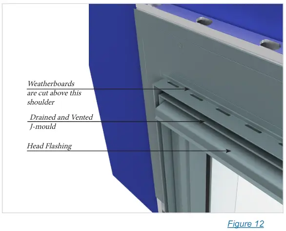
Head Cross Section
- Window head components must be assembled in strict sequence to achieve correct installation.
- The J-mould at the head must be a drained and vented bottom cladding base mould (BOC Base).
- The head flashings width is cut to suit, supplied by the joinery supplier.
- See window details for component location and sizing.
- Where flashings Cover the Alpha Rail ® fixing Tracks, it is advised to scribe or mark fixing locations for easy identification later.

Head Flashings
- Jamb components are cut to the height of the top of the U-section of the J-mould so that the J-mould will butt into the jamb J-Mould. See Fig S10
- The flashing Tape must extend all the way across the Jamb Flashing
- The Jamb Flashing extends above the rest of the jamb assembly to the height of the top flange of the head flashing.
- The head flashing is cut 15mm long at each end and cut and bent to form an end dam 15mm high and 20 mm deep.

Drained J-mould at Head
- The Head drained J-mould is cut between the jamb J-moulds and fastened to the batten above the opening.
- Fastenings are SS 8g x 20mm Countersunk screws.
- The Jamb J-mould base and head J-mould base are mitred at 45° to accurately fit.

Face Trim Installation at Head
Facings are mitred at the corners and clipped firmly into place.
Board Terminations
Ripped Weatherboard Termination
METHOD 1
- Where cut weatherboards occur, 100mm long clamp channels are attached to the Clamp Zed with two 4mm pop rivets.
- The Clamps are placed at the same centres as the horizontal battens.
- The back legs of the weatherboard will need to be removed where they interfere with clamps.

METHOD 2
- 100mm long clamp channels are pre drilled with 10mm clearance holes to allow screwing of clamps to the J-mould flange 12mm away from the J-mould return. One clamp channel fixed to each fixing location.
- When weatherboards are fixed in place the Clamp Z is cut to length and screwed in place clamping the weatherboard in place hard against the clamp channels.

External Corner
-
Fitting the Base Flashing
-
External Corner Base and Bottom of Cladding Base are fitted and screwed to the battens with SS 8g x 16mm countersunk screws at 1000mm centres.
-
Before fitting, the Bottom Base is cut to fit around the External Corner Base flange so that the flanges of both are flush.
-
The cladding Base is mitred at the corner with a square cut from the outer corner to allow the External cover mould to run past
-
Ending a wall
-
Either method 1 or 2 for Ripped Weatherboard Termination is applicable as referenced on page 17/18.
-
Starting an External Corner
Walls panels are started with a starter placed hard to the external corner base and fixed in the same manner as a weatherboard fixed to the battens.
The bottom of the weatherboards are placed 6mm off the Cladding Base Mould sitting above the shoulder provided.- Starting at external corners is easiest, but careful attention should be paid to openings and internal corner locations to determine best start point.
-
Fitting the Face Trims
When the weatherboard installation is complete, the external corner trim is cut to length and clipped into position.
The ends of the bottom trims are cut to a 45° angle to fit together benefit the corner facing and clipped into position.
Internal Corners
- Fitting the Base Flashings
- Internal Bottom of Cladding Base are fitted and screwed to the battens with 8g x 16mm countersunk screws and 1000mm centred.
- Before fitting, the Bottom Base is cut to fit around the External Corner Base flange so that the flanges of both are flush and fixing is provided for both the corner base and the J-mould base.
- Ending a wall on an
- Internal Corner
- See Ripped with Beads pages 17/18. It is recommended to use Method 2 for finishing an internal corner.

- See Ripped with Beads pages 17/18. It is recommended to use Method 2 for finishing an internal corner.
- Fitting the Face Trims
- When the weatherboard installation is complete, the Internal Corner Face is cut to length and clipped into position.
- The ends of the bottom facings are cut to a 45° angle to fit together beneath the corner facing and clipped into position.

Simplified Typical Detail
(See website for comprehensive typical details downloads)
Vertical Wall Join
Vertical Break
External Corner Detail


- The starter sets the run lines
- Extra care should be given to ensure this is plumb and straight.
- Location within the corner has 5mm tolerance.
Internal Wall Detail


Internal Critical Dimension
The 18mm dimension shown is critical to enable fixing of the weatherboard in
in place using option 1 board termination.
Window Jamb Detail (With WANZ Bar)
 Window
Jamb Detail (Without WANZ Bar)
Window
Jamb Detail (Without WANZ Bar)

Window Head Detail (With WANZ Bar)

Window Head Detail (Without WANZ Bar)


Window Sill Detail (With WANZ Bar)


Window Sill Detail (Without WANZ Bar)


Foundation Bottom of Cladding

Horizontal Joint (Intertstory)


Horizontal Joint


Fascia to Soffit


Fascia to Soffit – Parallel Aligned


Soffit to Wall
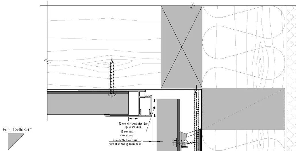

Parallel Aligned Soffit to Wall


90° Soffit to Wall


Flat Sheet Soffit to Wall <90°


Flat Sheet Soffit to Wall >90°
 JAN 2024 [R1V4]
References
Read User Manual Online (PDF format)
Read User Manual Online (PDF format) >>