LOGNWEI PS-3010DF DC Power Supply Variable 30V 10A Bench Power Supply Instruction Manual
- June 15, 2024
- LOGNWEI
Table of Contents
 ⁜ LONGWEI INSTRUMENTS CO.,LTD
LW DC POWER SUPPLY
PS-3010DF / PS-305DF
PS-3010DF DC Power Supply Variable 30V 10A Bench Power Supply
Step chart for Constant Voltage Output (C. V. Mode)

 CStep chart for Constant Current Output (C. C.
Mode)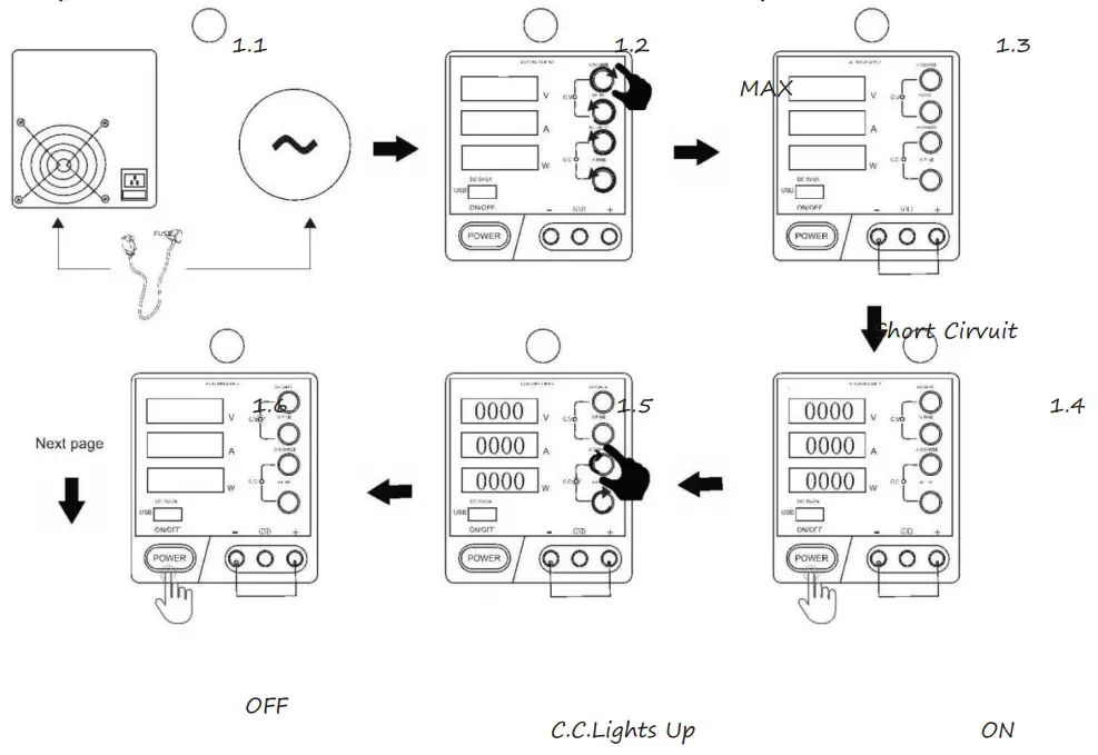

Introduction
Dear customer,
Thank you for purchasing this product.
This product complies with the statutory national and European requirements.
To maintain this status and to ensure safe operation,
you as the user must observe these operating instructions!
These operating instructions contain important notes on commissioning and
handling. Retain these operating instructions for reference!
Intended use
This power supply is DC regulated power supply. It can output and display
constant voltage and constant current, combined
with a 5V voltage output with USB interface, equipped with cooling fan, over
temperature protection, overload protection.
Controls and Indicators

- Output voltage display
- Output current display
- Output power display
- USB power supply
- Power ON/OFF switch
- C.V. Indicator (Constant voltage mode indicator)
- C.C. Indicator (Constant current mode indicator)
- Coarse voltage regulator (To coarsely adjust output voltage)
- Fine voltage regulator (To slightly adjust output voltage)
- Coarse current regulator (To coarsely adjust output urrent)
- Fine current regulator (To slightly adjust output current)
- Negative output terminal
- Ground output terminal
- Positive output terminal
- Fan
- Power Connection
- Concealed fuse box (Open the back cover to get to the fuse)
Operation
Please strictly follow the instruction to avoid machine malfunction or
possible injury caused by electricity.
Constant Voltage Mode (C.V. Mode)
Step-by-step illustration on Page Ⅰ-Ⅱ
- Connect the three-wire power cord with a Standard AC outlet.
- Turn all 4 knobs (Coarse Voltage Regulator, Fine Voltage Regulator, Coarse Current Regulator, Fine Current Regulator) anti-clockwise to minimum position before using.
- Press the power switch. The power indicator (red LED) on the front panel will automatically light.
- Turn the Coarse Current Regulator clockwise to maximum position until the C.V. indicator lights up.
- Turn the Coarse Voltage Regulator and Fine Voltage Regulator clockwise to that you are desirous of output voltage value.
- Always press the power switch and shut it off before connecting the positive output terminal and negative output terminal with a load or similar component. Then switch it on.
- The output voltage will be displayed. Current can’t be changed in C.V. Mode.
NOTE: The working mode is decided by the load current and the traction current. In Constant Voltage Mode, the current is determined by the load. The larger the load, the smaller is the current.
Constant Current Mode (C.C. Mode)
Step-by-step illustration on Page III- Ⅳ
- Connect the three-wire power cord with a Standard AC outlet.
- Turn the Coarse Voltage Regulator clockwise to maximum position and the Coarse Current Regulator and Fine Current Regulator anti-clockwise to minimum position.
- Connect the positive output terminal and the negative output terminal with a wire (one included) and bring it to a short circuit.
- Press the power switch to turn it on. The C.C. indicator lights up, which means it’s on C.C. Mode.
- Turn the Coarse Current Regulator and Fine Current Regulator clockwise to that you are desirous of output current value.
- Always press the power switch and shut it off before connecting the positive output terminal and negative output terminal with a load or similar component. Then switch it on.
- The output current will be displayed. Voltage can’t be changed in C.C. Mode.
- NOTE: The working mode is decided by the load current and the traction current. In Constant Current Mode, the voltage is determined by the load. The smaller the load, the smaller the voltage.
Technical parameters
| Rated working conditions: | 110V-130V, 50Hz / 220V-240V, 60Hz |
|---|---|
| Output Current Range: | 0-10A/5A |
| Output Voltage Range: | 0-30V |
| USB interface: | 5A,2A |
| Power supply effect : | CV≤0.1%+10mV, CC≤0.1%+10mA |
| Load effect : | CV≤0.1%+5mV, CC≤0.1%+10mV |
| Ripple and noise: | CV≤20mV r.m.s., CC≤20mA r.m.s. |
| Display mode: | 4-digit LED display |
| Display accuracy: | ± 0.1% ± 1 |
| Working conditions: | -10 °C ~ 40 °C, Relative humidity: <80% |
| Storage conditions: | -20 °C ~ 80 °C, Relative humidity: <70% |
| Dimensions: | 285x128x145mm. |
Maintenance
Repair
Do not attempt to repair or service your instrument unless you are qualified
to do so and have the relevant calibration,
performance test and service information.
Replacing the Fuse
Turn off the power switch, remove the power line cord from the power socket
and disconnect the test leads at output terminals
before replacing the fuse. Replace it only with same type of fuse.
Cleaning
To clean the DC Power Supply, use a soft cloth dampened in a solution of mild
detergent and water. Do not spray cleaner directly onto the device, since it
may leak into the cabinet and cause damage. Do not use chemicals containing
benzine,
benzene, toluene, xylene, acetone, or similar solvents. Do not use abrasive
cleaners on any portion of the power supply.
Read User Manual Online (PDF format)
Read User Manual Online (PDF format) >>