MOLLLET VF62 Compact Sensor User Manual
- June 8, 2024
- MOLLLET
Table of Contents
- MOLLLET VF62 Compact Sensor
- Use of the device
- Receiving department and storage
- Information for use
- Technical data
- Electrical data
- Versions/Dimensions
- Possibilities for installation
- Setting of sensitivity
- Maintenance
- Special conditions and instructions for safe application
- References
- Read User Manual Online (PDF format)
- Download This Manual (PDF format)
MOLLLET VF62 Compact Sensor
Please, read and obey these safety instructions and the complete operating manual.
Safety instructions
- The installation, initial operation and maintenance must be done by a qualified expert with electrical know-how.
- Check before installation whether the measuring device is in compliance with the specification of the point of measurement as process and ambient temperature as well as the measuring range.
- Use in potentially explosive atmospheres only devices with identification marking.
- For the electrical connection take notice of the local and statutory rules and regulations and/or the VDE 0100.
- Consider the data of the name plate on the device.
- A fuse (max. 4 A) and a main switch have to be connected in series to the voltage supply.
- Switch off the voltage supply before you open the measuring devive (dangerous voltages in case of contact).
- Check the cable entry, cable gland and clamping nut, to see if they are sitting correctly and are sealed.
- Put the device into operation only when the unit is closed and the cover sealing is intact.
- Changes and repairs of the device are allowed only in so far as it is permitted in the operating instructions.
Prior to the use of the device in potentially explosive atmospheres please, read and obey the Special conditions and guidance for safe use in the attached Explosions protection information and observe the operating instruction.
Use of the device
- Intended use
- The device is used as a level limit switch for bulk solids in silos, bins and so on.
- Normal operation
- Please operate the measuring device only according the intended use.
- Use the measuring device only within the specified temperature ranges for process and ambience.
- Protect the electronics compartment against pollution.
- In case the measuring device becomes damaged, please stop operation immediately.
- Improper use
- Ignoring safety regulations and operating instruction.
- Operation of the measuring device in inappropriate use.
- Installation of spare parts that are no original parts.
- Removal, addition or modification of components as far as it is not described in the documentation of the manufacturer.
- Violation of applicable standards and laws.
Data of manufacturer
Manufacturer MOLLET
Füllstandtechnik GmbH
Address Industriepark RIO 103 74706 Osterburken Germany
Name of part MOLOSvibro
Vibro level indicator
Type VF6 …
Receiving department and storage
- Receipt of goods
- Please check whether packaging or content are damaged.
- Please check whether the supplied goods are incomplete or do not comply the requirements as set out in your order.
- Storage
- For storage and transportation, the measuring device has to be packed shock-resistant.
- Store the device at a place protected against moisture and dust.
- Take care that the probe will not be bended.
- Temperature range for storage -40 °C … +85 °C
Application (intended use)
The MOLOSvibro of the VF6. series is intended for the use as level limit
switch in silos and vessels.
For all bulk solids with a minimum density of 0.02 t/m³.
For application in all industry sectors.
Function
- Oscillation of the mini vibration rod with a resonance frequency of approx. 460 Hz is stimulated by the electronic.
- As soon as the vibration rod has been covered by bulk solids, the oscillation will be damped.
- The electronic detects the damping and switches the relay signal.
- If the filling level sinks below the vibration rod, the rod starts vibrating with its resonance frequency again and the relay switches back.
Information for use
Please obey the following for the use of the Vibro level indicator:
-
Switch point dependent of bulk density (t/m³; kg/l):
- with heavy bulk solids only the tip of the rod has to be covered for damping the vibration.
- with light bulk solids the complete rod has to be covered for damping the vibration.
-
In order to keep the ambient temperature of the PCB below +60°C please
- protect the housing from direct sunlight by installing a sun shield.
protect the housing against temperature transfer from the silo in cases the process temperature exceeds 60°C by installation of a heat barrier between the enclosure and the bin wall or use the high temperature option E1.
- protect the housing from direct sunlight by installing a sun shield.
-
The measuring device must not be mounted in or near the filling stream. The falling bulk solids could damage the probe.
Technical data

Electrical data
Wide range electronic C8
- Supply voltage 20 … 250 V AC / DC
- Power consumption € 3 VA / 3 W
- Signal relay potential free change-over-contact (SPDT)
- Capacity of contact 5 A / 250 V AC or 150 W at DC
- Connection clamps maximum 1.5 mm²
Versions/Dimensions
- VF62 Compact sensor

- VF63 Rod extension sensor

- VF65 Suspension cable sensor

- E1 High temperature up to 150 °C
Possibilities for installation

Side mounting or vertical mounting:
- VF62 and VF63 can be mounted either from the side or vertical.
- For side mounting it is recommended to screw the measuring device slightly downwards (approx. 20°) so that bulk solids can flow off.
- The measuring device has to be mounted in such a way that the filling stream cannot damage it.
- In case the filling stream reaches the probe nevertheless, it has to be protected by a suitable protection roof.
- If the probe is used as empty indicator in the lower area of bins/silos with heavy bulk solids, a protection roof has always to be installed.
- VF65 is suitable for top mounting only.
- A suitable sealing, (like Teflon tape), must be applied onto the thread and the VF has to be s crewed into the provided socket with a 36 mm open end wrench.
Attention: Do not screw by turning the housing!
Protection against bulk solids crashing down upon the rod
Level indicators must not be affected by flying bulk goods particles e.g. from
injection pies, filling pipes or down pipes. Therefore the bulk solids stream
should be directed or redirected accordingly, or the level indicator should be
placed so that bulk solids cannot impact directly onto the probe and vibration
rod.

Flush installation
Protection against heavy load
If needed, a protection roof or a stable deflector has to be installed inside
the container, in order to protect the probe and the rod against impinging
bulk solids.
Between protection roof and the probe has to be enough space that bulk solids
could penetrate but not jam.
Protection against moisture by alignment of cable glands
The cable glands must always point downwards to prevent moisture seeping inside the housing. If the housing is not in the correct position after the probe has been firmly screwed into the bin wall, proceed as follows:
- remove the screw in the middle of the cover (4 mm Allen key) and open the housing.
- resolve t he spacer nut M6 in the center of the enclosure (10 mm wrench) a little bit until the enclosure is turnable.
- turn the housing into the correct position so that the cable glands are pointing downwards.
- tighten the spacer nut M6 again, torque 3 to 4 Nm.
- put on the housing cover and tighten the screw, torque 3 Nm.
Cable ducts which are not used have to be sealed!
Allowed temperatures
- Ambient temperature at the probe (process temperature) T(process) -20°C … +80°C
- Ambient temperature at the electronic housing Ta -20°C … (+50°C) +60°C
Due to the process temperature of 80 °C reduced maximum allowed ambient temperature at the electronic housing
Maximum allowed ambient temperature at the electronic housing is dependent of the process temperature.
(see diagram)
Bulk solids temperatures up to 150 °C
The high temperature option E1 enables the use of the level indicators for
bulk solids temperatures up to 150 °C.
- in order to protect the electronic against overheating by heat transfer from the process, a decoupling for high temperatur E1 is installed between probe and electronic housing.
- use for process temperatures above 80 °C only level indicators with the high temperature option E1.
- due to high process temperatures the maximum allowed ambient temperature at the electronic housing is reduced (see diagram)
- please mind for exchange of electronics that only PCBs with the marking „Special Model HT“ may be used.
Electrical connection Wide range electronic C8

High alarm and low alarm sensor
MOLOSvibro level indicator of the VF6. series can be used for high level and
low level alarm.
- The function can be adjusted with a jumper on the electronic board.
- The switching status is indicated by a red LED on the electronic board, like it is explained below.
Setting of sensitivity
Adjustment by jumper at A – B – C
Position A: highest sensitivity level for light bulk solids with a
density above 0.02 kg/l
Position B: standard sensitivity level (factory setting) sufficient for
most bulk solids.
Position C: lowest sensitivity level for heavy materials with high
densities which may form a deposit on the vibrating rod.
Light materials can not be detected at this setting!
Maintenance
The Vibro level indicators require no maintenance.
- For applications with materials that are a little bit sticky we recommend to clean the vibrating blade of the instrument in certain periods of time.
- If the instruments are exposed to corrosive atmosphere, they must be inspected in certain periods of time regarding corrosion of probe and enclosure in order to ensure the tightness of the instruments.
Disposal
- Level indicator VF can be recycled.
- Disposal of the VF is subject to the environmental legislation of the respective country in effect for the operator’s premises.
Returns
-
Remove all adherent material residues of filling material from the measuring device. Be aware of seal grooves and cracks where material residues could stick.
In particular if the bulk goods or liquids has been dangerous to health,e. g. flammable, toxic, caustic or cancer-producing. -
Furthermore please state:
- Chemical and physical characteristics of the bulk goods or liquid
- Description of the application
- Description of the failure occurred
- Operating time of the measuring device.
Vibro level indicators
Level limit switches for bulk goods VF6.
Explosion protection information and supplement to the operating instructions
Type plate details with option B11
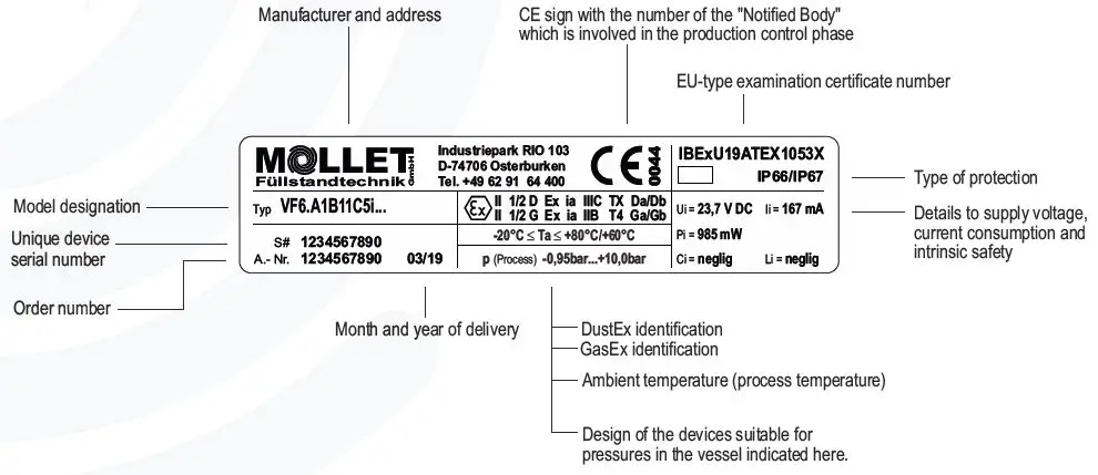
Marking in accordance with ATEX and DIN EN IEC 60079-0
Vibro level indicator for use at the boundary from zone 20 to zone 21.

Vibro level indicator for use at the boundary from zone 0 to zone 1.

Order code VF62A1B11C5i… and VF63A1B11C5i…
Marking: II 1/2 D|
II 1/2 G
Equipment category appropriation by zones
Vibro level indicator for use at the boundary from zone 20 to zone 21 and for
use at the boundary from zone 0 to zone 1.
Ambient temperatures Ta
The ambient temperature Ta defines the maximum operating temperature of the
indicators. Inside the vessel this is process temperature (the air or the bulk
goods temperature) nearby the device.
Maximum surface temperature T, TX
The maximum surface temperature T means the hottest point at the equipment.
The device equates to temperature class
Note:
Probe and vibration rod produce no increase of temperature, but they are able
to take high temperatures from inside of the vessel and forward it.
Due to this, the surface temperature has to be determined according to the
process temperature (temperature of bulk solids or ambient) inside of the
vessel.
Pressure, vacuum
Design of the devices is suitable for indicated pressures in the vessel.
These pressures are outside of the range for atomospheric conditions defined
in the guidance to the ATEX-Product-Directive.

maximum authorised process temperature
-20 °C € Ta € +80 °C/€+60 °C
maximum authorised ambient temperature at the electronic housing
Order code VF65A1B11C5i…
Marking: II 1/2 D
II 1/2 G
Equipment category appropriation by zones
Vibro level indicator for use at the boundary from zone 20 to zone 21 and for
use at the boundary from zone 0 to zone 1.
Ambient temperatures Ta
The ambient temperature Ta defines the maximum operating temperature of the
indicators. Inside the vessel this is process temperature (the air or the bulk
goods temperature) nearby the device.
Maximum surface temperature T, TX
The maximum surface temperature T means the hottest point at the equipment.
The device equates to temperature class T 4
Note:
Probe and vibration rod produce no increase of temperature, but they are able
to take high temperatures from inside of the vessel and forward it.
Due to this, the surface temperature TX has to be determined according to the
process temperature (temperature of bulk solids or ambient) inside of the
vessel.
Pressure, vacuum
Design of the devices is suitable for indicated pressures in the vessel.
These pressures are outside of the range for atomospheric conditions defined
in the guidance to the ATEX-Product-Directive.


maximum authorised process temperature
-20 °C € Ta € +70 °C/€+60 °C
maximum authorised ambient temperature at the electronic housing
Inside high process temperature, outside ambient temperature
Order code VF62A1B11C5i…E1… and VF63A1B11C5i…E1…
Marking: II 1/2 D
II 1/2 G
Equipment category appropriation by zones
Vibro level indicator for use at the boundary from zone 20 to zone 21 and for
use at the boundary from zone 0 to zone 1.
Ambient temperatures Ta
The ambient temperature Ta defines the maximum operating temperature of the
indicators. Inside the vessel this is process temperature (the air or the bulk
goods temperature) nearby the device.
Maximum surface temperature T, TX
The maximum surface temperature T means the hottest point at the equipment.
The device equates to temperature class T 4
Note:
Probe and vibration rod produce no increase of temperature, but they are able
to take high temperatures from inside of the vessel and forward it.
Due to this, the surface temperature TX has to be determined according to the
process temperature (temperature of bulk solids or ambient) inside of the
vessel.
Pressure, vacuum
Design of the devices is suitable for indicated pressures in the vessel.
These pressures are outside of the range for atomospheric conditions defined
in the guidance to the ATEX-Product-Directive.

maximum authorised process temperature
-20 °C € Ta € +150 °C/€+60 °C
maximum authorised ambient temperature at the electronic housing
Special conditions and instructions for safe application
- The installation, maintenance, initial operation, removal and repair have to be controlled resp. checked by an “authorized person” for explosion protection and has to be done according to the specifications in the operating instructions manual.
- According to DIN EN 61010-1 a main switch for the supply and evaluation device has to be installed nearby and has to be made visible as such. It must be able to interrupt the power supply and relay circuit with this main switch.
- For protection against surge voltages a overvoltage filter has to be installed accordingly.
- For the electrical connection you have to take notice of the local and statutory requirements and/or the VDE 0100 as well as the additional requirements for the ignition protection type „i“ – intrinsic safety according EN 60079-14 for associated equipments without galvanic isolation.
- The vibro level indicator is a category 1 equipment that has to be installed in such a way that sparks can not be generated by shocks- The vibro level indicator is a category 1 equipment that has to be installed in such a way that sparks can not be generated by shocks onto or friction at the aluminium housing.
- The power supply must be provided by the associated equipment „Supply and evaluation device VF-VEC8-B22″ only.

- Take notice of the specifications on the data plate.
- Standards for the connection of intrinsic safe circuits according to EN 60079-14 must be observed.
- The associated equipment „Supply and evaluation device VF-VEC8-B22″ has to be installed in a room without potentially explosive atmosphere (control cabinet).
- As soon as the device will be brought into the explosion hazardous area it has to be mounted immediately at the intended place and a cable has to be brought into the cable gland.
- Please check if the cable gland have loosened during mounting process or transport. When it is loosened, it has to be fixed again with a torque of 3.75 Nm.
- To secure the type of protection, the screw nut of the cable gland has to be fixed at the installation with a minimum torque of 2.7 Nm. ATTENTION! If it will be fastened too strong, the IP-protection can be affected.
- The device has to be grounded and the ground connection of the device has to be installed in such a way that mechanical damage will be excluded.
- The device may put into operation with built-in cap-sealing and when it is closed, only.
- Remove the dust from the housing before you open it and make sure that no dust turbulences exist.
- Please check position and intactness of all gaskets before you close the device.
- Tightening torque of distance nut M6x40: 3 … 4 Nm and of the lid screw M6x16: 3 Nm.
- The maximum authorised temperatures for process (bulk solids) and ambience have to be observed.
- Take notice of the requirements of DIN EN 60079-11, DIN EN 60079-17 and DIN EN 1127-1, especially regarding the dust deposits and temperatures and follow the pertinent rules and regulations.
Type plate details

EU-Declaration of Conformity
Wir/We MOLLET Füllstandtechnik GmbH
Industriepark RIO 103
D-74706 Osterburken
Tel. 06291 64400 Fax 06291 9846
declares under our sole responsibility, that the product:
Vibro-Füllstandanzeiger / Vibro level indicator
Typ/Type VF …
conforms with the following European directives:
EMV-Richtlinie EMC directive 2014/30/EU
Niederspannungsrichtlinie Low voltage directive 2014/35/EU
Applied harmonized standards or normative documents
DIN EN 61326-1:2013
DIN EN 61010-1:2020
And the devices with – marking conform additional with the following European directive:
ATEX-Richtlinie ATEX directive 2014/34/EU
Depending on the design applied harmonized standards or normative documents:
DIN EN IEC 60079-0:2019 DIN EN 60079-31:2014
EU-Type Examination Certificate: IBExU19ATEX1052
Ausgestellt von:.
Issued by: IBExU Institut für Sicherheitstechnik GmbH, 09599 Freiberg (0637)
Qualitätssicherung:
Quality assurance: TÜV NORD CERTGmbH, 30159 Hannover (0044)
Osterburken, den 20.03.2021
Wolfgang Hageleit
Geschäftsführer / Managing director
08 VF6-EIG-08 06/21 © by MOLLET Explosion protection information MOLLET
D-74706 Osterburken
Tel. +49 6291 6440-0 www.mollet.de
References
Read User Manual Online (PDF format)
Read User Manual Online (PDF format) >>