mitsubishielectric MXZ-4F80VGD Split-type Air-Conditioner Instruction Manual
- June 5, 2024
- mitsubishielectric
Table of Contents
Split-type Air-Conditioner
MXZ-4F80VGD
MXZ-5F100VGD
Installation Manual
For INSTALLER
- This manual only describes the installation of an outdoor unit.
When installing the indoor unit, refer to the installation manual of the indoor unit.
Required Tools for Installation
Phillips screwdriver: Flare tool for R32, R410A
Level: Gauge manifold for R32, R410A
Scale: Vacuum pump for R32, R410A
Utility knife or scissors: Charge hose for R32, R410A
Torque wrench: Pipe cutter with a reamer
Wrench (or spanner)
4 mm hexagonal wrench
BEFORE INSTALLATION
MEANINGS OF SYMBOLS DISPLAYED ON INDOOR UNIT AND/OR OUTDOOR UNIT
| WARNING
(Risk of fire)
| This unit uses a flammable refrigerant.
If refrigerant leaks and comes in contact with fire or heating part, it will create harmful gas and there is risk of fire.
---|---|---
| Read the OPERATING INSTRUCTIONS carefully before operation.
| Service personnel are required to carefully read the OPERATING INSTRUCTIONS
and INSTALLATION MANUAL before operation.
| Further information is available in the OPERATING INSTRUCTIONS, INSTALLATION
MANUAL, and the like.
1-1. THE FOLLOWING SHOULD ALWAYS BE OBSERVED FOR SAFETY
- Be sure to read “THE FOLLOWING SHOULD ALWAYS BE OBSERVED FOR SAFETY” before installing the air conditioner.
- Be sure to observe the warnings and cautions specified here as they include important items related to safety.
- After reading this manual, be sure to keep it together with the OPERATING INSTRUCTIONS for future reference.
- Equipment complying with IEC/EN 61000-3-12.
WARNING (Could lead to death, serious injury, etc.)
-
Do not install the unit by yourself (user).
Incomplete installation could cause fire or electric shock, injury due to the unit falling, or leakage of water. Consult the dealer from whom you purchased the unit or a qualified installer. -
Perform the installation securely referring to the installation manual. Incomplete installation could cause fire, electric shock, injury due to the unit falling, or leakage of water.
-
When installing the unit, use appropriate protective equipment and tools for safety.
Failure to do so could cause injury. -
Install the unit securely in a place that can bear its weight of the unit.
If the installation location cannot bear the weight of the unit, the unit could fall causing injury. -
Electrical work should be performed by a qualified, experienced electrician, according to the installation manual. Be sure to use an exclusive circuit. Do not connect other electrical appliances to the circuit.
If the capacity of the power circuit is insufficient or there is incomplete electrical work, it could result in a fire or an electric shock. -
Do not damage the wires by applying excessive pressure with parts or screws.
Damaged wires could cause fire or electric shock. -
Be sure to cut off the main power in case of setting up the indoor P.C. board or wiring works.
Failure to do so could cause electric shock. -
Use the specified wires to connect the indoor and outdoor units securely and attach the wires firmly to the terminal block connecting sections so the stress of the wires is not applied to the sections. Do not extend the wires, or use the intermediate connection.
Incomplete connecting and securing could cause fire. -
Do not install the unit in a place where inflammable gas may leak.
If gas leaks and accumulates in the area around the unit, it could cause an explosion. -
Do not use the intermediate connection of the power cord or the extension cord and do not connect many devices to one AC outlet.
It could cause a fire or an electric shock due to defective contact, defective insulation, exceeding the permissible current, etc. -
Be sure to use the parts provided or specified parts for the installation work.
The use of defective parts could cause an injury or leakage of water due to a fire, an electric shock, the unit falling, etc. -
When plugging the power supply plug into the outlet, make sure that there is no dust, clogging, or loose parts in both the outlet and the plug. Make sure that the power supply plug is pushed completely into the outlet. If there is dust, clogging, or loose parts on the power supply plug or the outlet, it could cause electric shock or fire. If loose parts are found on the power supply plug, replace it.
-
Attach the electrical cover to the indoor unit and the service panel to the outdoor unit securely.
If the electrical cover of the indoor unit and/or the service panel of the outdoor unit are not attached securely, it could result in a fire or an electric shock due to dust, water, etc. -
When installing, relocating, or servicing the unit, make sure that no substance other than the specified refrigerant (R32) enters the refrigerant circuit.
Any presence of foreign substances such as air can cause abnormal pressure rise and may result in explosion or injury. The use of any refrigerant other than that specified for the system will cause mechanical failure, system malfunction, or unit breakdown. In the worst case, this could lead to a serious impediment to securing product safety. -
Do not discharge the refrigerant into the atmosphere. If refrigerant leaks during the installation, ventilate the room. Check that the refrigerant does not leak after the installation has been completed.
If refrigerant leaks and comes in contact with fire or heating part of such a fan heater, kerosene heater, or cooking stove, it will create harmful gas. Provide ventilation in accordance with EN378-1. -
Check that the refrigerant gas does not leak after the installation has been completed.
If the refrigerant gas leaks indoors and comes into contact with the flame of a fan heater, space heater, stove, etc., harmful substances will be generated. -
Use appropriate tools and piping materials for installation.
The pressure of R32 is 1.6 times more than R22. Not using appropriate tools or materials and incomplete installation could cause the pipes to burst or injury. -
When pumping down the refrigerant, stop the compressor before disconnecting the refrigerant pipes.
If the refrigerant pipes are disconnected while the compressor is running and the stop valve is open, air could be drawn in and the pressure in the refrigeration cycle could become abnormally high. This could cause the pipes to burst or injury. -
When installing the unit, securely connect the refrigerant pipes before starting the compressor.
If the compressor is started before the refrigerant pipes are connected and when the stop valve is open, air could be drawn in and the pressure in the refrigeration cycle could become abnormally high. This could cause the pipes to burst or injury. -
Fasten a flare nut with a torque wrench as specified in this manual.
If fastened too tight, a flare nut may break after a long period and cause refrigerant leakage. -
The unit shall be installed in accordance with national wiring regulations.
-
Earth the unit correctly.
Do not connect the earth to a gas pipe, water pipe, lightning rod or telephone earth. Defective earthing could cause electric shock. -
Be sure to install an earth leakage breaker.
Failure to install an earth leakage breaker may result in electric shock or fire. -
When using a gas burner or other flame-producing equipment, completely remove all of the refrigerants from the air conditioner and ensure that the area is well-ventilated.
If the refrigerant leaks and comes in contact in fire or heating part, it will create harmful gas and there is risk of fire. -
Do not use means to accelerate the defrosting process or to clean, other than those recommended by the manufacturer.
-
The appliance shall be stored in a room without continuously operating ignition sources (for example open flames, an operating gas appliance or an operating electric heater).
-
Do not pierce or burn.
-
Be aware that refrigerants may not contain an odor.
-
Pipe work shall be protected from physical damage.
-
The installation of pipe-work shall be kept to a minimum.
-
Compliance with national gas regulations shall be observed.
-
Keep any required ventilation openings clear of obstruction.
-
Do not use low-temperature solder alloy in case of brazing the refrigerant pipes.
-
Servicing shall be performed only as recommended by the manufacturer.
-
Do not alter the unit. It may cause fire, electric shock, injury or water leakage.
-
When opening or closing the valve below freezing temperatures, refrigerant may spurt out from the gap between the valve stem and the valve body, resulting in injuries.
CAUTION
(Could lead to serious injury in particular environments when operated
incorrectly.)
-
Install an earth leakage breaker depending on the installation place.
If an earth leakage breaker is not installed, it could cause electric shock. -
Perform the drainage/piping work securely according to the installation manual.
If there is defect in the drainage/piping work, water could drop from the unit, soaking and damaging household goods. -
Do not touch the air inlet or the aluminum fins of the outdoor unit.
This could cause injury. -
Do not install the outdoor unit where small animals may live.
If small animals enter and touch the electric parts inside the unit, it could cause a malfunction, smoke emission, or fire. Also, advise user to keep the area around the unit clean. -
Do not operate the air conditioner during interior construction and finishing work, or while waxing the floor.
Before operating the air conditioner, ventilate the room well after such work is performed. Otherwise, it may cause volatile elements to adhere inside the air conditioner, resulting in water leakage or scattering of dew.
1-2. SPECIFICATIONS
Model
| Power supply 1| Wire specifications 2| Pipe length and height difference
3, 4, 5, 6, 7, 8
---|---|---|---
Rated Voltage| Fre- quency| Breaker capacity| Power supply| Indoor / out- door
connect- ing wire| Max. pipe length per indoor unit / for multi-system| Max.
height
difference
| Max. no. of bends per indoor unit / for multi system
MXZ-4F80VGD| 220 V 60 HZ
230 V 50 HZ
| 25 A| 3-core
2.5 mm2
| 4-core 1.0 / 1.5 mm2| 25 m / 70 m| 15 m| 25 / 70
MXZ-5F100VGD| 25 m / 80 m| 25 / 80
Model| Maximum amount of refrigerant charge| Factory-charged
refrigerant amount
| Connectable number
of indoor units
---|---|---|---
MXZ-4F80VGD| 2.4 kg| 2.4 kg| 1 ~ 4 9
MXZ-5F100VGD| 1 ~ 5 9
- Connect to the power switch which has a gap of 3 mm or more when open to interrupt the source power phase. (When the power switch is shut off, it must interrupt all phases.)
- Use wires in conformity with design 60245 IEC 57. Use the indoor/outdoor connecting wire in conformity with the wire specifications specified in the installation manual of the indoor unit.
- Never use pipes with thickness less than specified. The pressure resistance will be insufficient.
- Use a copper pipe or a copper-alloy seamless pipe.
- Be careful not to crush or bend the pipe during pipe bending.
- Refrigerant pipe bending radius must be 100 mm or more.
- Insulation material : Heat-resisting foam plastic 0.045 specific gravity
- Be sure to use the insulation of specified thickness. Excessive thickness may cause incorrect installation of the indoor unit and insufficient thickness may cause dew drippage.
- At least 2 indoor units must be connected when using the indoor unit with a capacity lower than 25 class.
1-3. SELECTING OPTIONAL DIFFERENT-DIAMETER JOINTS
If the diameter of the connection pipe does not match the port size of the
outdoor unit, use optional different-diameter joints according to the
following table.
(Unit: mm (inch))
Port size of the outdoor unit| Optional different-diameter joints (port size
of outdoor unit → diameter of connection pipe)
---|---
MXZ-4F80VGD| MXZ-5F100VGD| Liquid / Gas| 6.35 (1/4) → 9.52 (3/8) : PAC-493PI
9.52 (3/8) → 12.7 (1/2) : MAC-A454JP-E
9.52 (3/8) → 15.88 (5/8) : PAC-SG76RJ-E
12.7 (1/2) → 9.52 (3/8) : MAC-A455JP-E
12.7 (1/2) → 15.88 (5/8) : MAC-A456JP-E
Refer to the installation manual of the indoor unit for the diameter of the connection pipe of the indoor unit.
A UNIT| 6.35 (1/4) / 12.7 (1/2)
B – D UNIT| B – E UNIT| 6.35 (1/4) / 9.52 (3/8)
1-4. SELECTING THE INSTALLATION LOCATION
- Where it is not exposed to strong wind.
- Where airflow is good and dustless.
- Where rain or direct sunshine can be avoided as much as possible.
- Where neighbours are not annoyed by operation sound or hot air.
- Where rigid wall or support is available to prevent the increase of operation sound or vibration.
- Where there is no risk of combustible gas leakage.
- When installing the unit, be sure to secure the unit legs.
- Where it is at least 3 m away from the antenna of TV set or radio. Operation of the air conditioner may interfere with radio or TV reception in areas where reception is weak. An amplifier may be required for the affected device.
- Install the unit horizontally.
- Please install it in an area not affected by snowfall or blowing snow. In areas with heavy snow, please install a canopy, a pedestal and/or some baffle boards.
Note:
It is advisable to make a piping loop near outdoor unit so as to reduce vibration transmitted from there.
Note:
When operating the air conditioner in low outside temperature, be sure to
follow the instructions described below.
-
Never install the outdoor unit in a place where its air inlet/outlet side may be exposed directly to wind.
-
To prevent exposure to wind, install the outdoor unit with its air inlet side facing the wall.
-
To prevent exposure to wind, it is recommended to install a baffle board on the air outlet side of the outdoor unit.
Avoid the following places for installation where air conditioner trouble is liable to occur. -
Where flammable gas could leak.
-
Where there is much machine oil.
-
Where oil is splashed or where the area is filled with oily smoke (such as cooking areas and factories, in which the properties of plastic could be changed and damaged).
-
Salty places such as the seaside.
-
Where sulfide gas is generated such as a hot spring.
-
Where there is high-frequency or wireless equipment.
-
Where there is the emission of high levels of VOCs, including phthalate compounds, formaldehyde, etc., which may cause chemical cracking.
-
The appliance shall be stored so as to prevent mechanical damage from occurring.
FREE SPACE IS REQUIRED AROUND THE OUTDOOR UNIT
-
Obstacles above When there is no obstacle in front and on the sides of the unit, it is allowed to install the unit where an obstacle is above the unit only if the space shown in the figure is provided.
-
Front (blowing) side open As long as space indicated in the figure is provided, it is allowed to install the unit where obstacles are behind and on the sides of the unit. (No obstacle above the unit)

-
Obstacles in front (blowing) only When there is an obstacle in front of the unit as shown in the figure, open space above, behind, and on the sides of the unit is required.
-
Obstacles in front and behind The unit can be used by attaching an optional outdoor blowing guide (PAC-SH96SG-E) (but both sides and top are open).

-
Obstacles in front, behind and on side(s)
• When installing the unit in an area that is enclosed with walls such as a verandah, be sure to have enough space as shown below.
In this case, the air conditioning capacity and power consumption might deteriorate.
• When there is a lack of airflow or there is a possibility of becoming short cycle, install an outlet guide and make sure there is enough space behind of the unit.
• When installing two or more units, do not install the units in front or behind each other.

-
Service space Provide space for service and maintenance as shown in the figure.
 • R32 is heavier than air—as well
as other refrigerants—so tends to accumulate at the base (in the vicinity of
the floor). If R32 accumulates around base, it may reach
• R32 is heavier than air—as well
as other refrigerants—so tends to accumulate at the base (in the vicinity of
the floor). If R32 accumulates around base, it may reach
a flammable concentration in case room is small. To avoid ignition, maintaining a safe work environment is required by ensuring appropriate ventilation. If a refrigerant leak is confirmed in a room or an area where there is insufficient ventilation, refrain from using of flames until the work environment can be improved by ensuring appropriate ventilation.
• Refrigerant pipes connection shall be accessible for maintenance purposes.
• Install outdoor units in a place where at least one of the four sides is open, and in a sufficiently large space without depressions.

1-4-1. Minimum installation area for Outdoor units
If you unavoidably install a unit in a space where all four sides are blocked
or there are depressions, confirm that one of these situations (A, B or C) is
satisfied.
Note: These countermeasures are for keeping safety not for specification
guarantee.
A) Secure sufficient installation space (minimum installation area Amin).
Install in a space with an installation area of Amin or more, corresponding to
refrigerant quantity M (factory-charged refrigerant + locally added
refrigerant).
| M [kg] | Amin [m²] |
|---|---|
| 1.0 | 12 |
| 1.5 | 17 |
| 2.0 | 23 |
| 2.5 | 28 |
| 3.0 | 34 |
| 3.5 | 39 |
| 4.0 | 45 |
| 4.5 | 50 |
| 5.0 | 56 |
| 5.5 | 62 |
| 6.0 | 67 |
| 6.5 | 73 |
| 7.0 | 78 |
| 7.5 | 84 |

B) Install in a space with a depression height of [ 0.125 [m].
C) Create an appropriate ventilation open area.
Make sure that the width of the open area is 0.9 [m] or more and the height of
the open area is 0.15 [m] or more.
However, the height from the bottom of the installation space to the bottom
edge of the open area should be 0.125 [m] or less.
Open area should be 75% or more opening.
1-4-2. Minimum installation area for Indoor units
Install in a room with a floor area of Amin or more, corresponding to
refrigerant quantity M (factory-charged refrigerant + locally added
refrigerant).
Install the indoor unit so that the height from the floor to the bottom of the
indoor unit is h0; for wall mounted: 1.8 m or more; for ceiling suspended,
cassette and ceiling concealed: 2.2 m or more. When installing floor standing,
refer to the indoor unit installation manual. There are restrictions in
installation height for each model, so read the installation manual for the
particular unit.
For wall-mounted, ceiling suspended, cassette and concealed
| M [kg] | Amin [m²] |
|---|---|
| 1.0 | 3 |
| 1.5 | 4.5 |
| 2.0 | 6 |
| 2.5 | 7.5 |
| 3.0 | 9 |
| 3.5 | 12 |
| 4.0 | 15.5 |
| 4.5 | 20 |
| 5.0 | 24 |
| 5.5 | 29 |
| 6.0 | 35 |
| 6.5 | 41 |
| 7.0 | 47 |
| 7.5 | 54 |
| 
---|---
For floor standing (MFXZ)
| M [kg] | Amin [m²] |
|---|---|
| 1.00 | No requirements |
1.10
1.20
1.30
1.40
1.50
1.60
1.70
1.80
1.84| 3.63
1.90| 3.75
2.00| 3.95
2.10| 4.15
2.20| 4.34
2.30| 4.54
2.40| 4.74
1-5. INSTALLATION DIAGRAM
ACCESSORIES
Check the following parts before installation.
| (1) | Drain socket | 1 |
|---|---|---|
| (2) | Drain cap | 5 |
PARTS TO BE PROVIDED AT YOUR SITE
| (A) | Power supply cord* | 1 |
|---|---|---|
| (B) | Indoor/outdoor unit connecting wire* | 1 |
| (C) | Extension pipe | 1 |
| (D) | Wall hole cover | 1 |
| (E) | Piping tape | 1 |
| **** (F) | Extension drain hose (or soft PVC hose, 15 mm inner diam- eter or | |
| hard PVC pipe VP16) | 1 | |
| (G) | Refrigeration oil | Little amount |
| (H) | Putty | 1 |
| (I) | Pipe fixing band | 2 to 7 |
| (J) | Fixing screw for (I) | 2 to 7 |
| (K) | Wall hole sleeve | 1 |
| **** (L) | Soft PVC hose, 15 mm inner diameter or hard PVC pipe VP16 for drain | |
| socket (1) | 1 |
Note: * Place indoor/outdoor unit connecting wire (B) and power supply
cord (A) at least 1 m away from the TV antenna wire.
The “Q’ty” for (B) to (K) in the above table is the quantity to be used per
indoor unit.
Units should be installed by licensed contractors according to local code
requirements.
WARNING
To avoid risk of fire, embed or protect the refrigerant piping. External
damage on the refrigerant piping can be cause of fire.
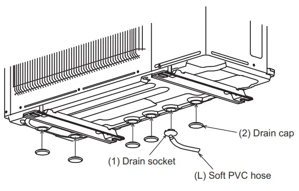
1-6. DRAIN PIPING FOR OUTDOOR UNIT
-
Perform the drain piping work only when draining from one place.
-
Provide drain piping before indoor and outdoor piping connection.
-
Attach the drain socket to one of the several drain holes.
Fix the drain socket into the drain hole of the base using the catches to secure it in place. -
Connect the soft PVC hose I.D.15 mm as shown in the illustration.
-
Make sure to provide drain piping with a downhill grade for easy drain flow.
-
Glue the drain caps to close all the other unnecessary holes with the glue (Prepare in the field).
 Note:
Note:
Apply the glue securely, as the glue (Prepare in the field) will work as seal
to prevent water from leaking.
Use the adhesive for the rubber and metal.
Attention
The outdoor unit is provided with several holes for drainage at the bottom to
make drainage easier.
The drain socket is used to close the unnecessary holes and centralize the
drainage when using the drain tube at the installation place.
Do not to use the drain socket in cold region. The drain tube can be frozen.
OUTDOOR UNIT INSTALLATION
2-1. INSTALLING THE UNIT
- Be sure to fix the unit’s legs with bolts when installing it.
- Be sure to install the unit firmly to ensure that it does not fall by an earthquake or a gust.
- Refer to the figure in the right for concrete foundation.
- Do not use the drain socket and the drain caps in the cold region. Drain may freeze and it makes the fan stop.
- Remove the tape on the panel when opening the package. (DO NOT remove the LABELS on the panel.)

2-2. CONNECTING WIRES FOR OUTDOOR UNIT
- Remove the service panel and the cable cover.
- Pass the indoor/outdoor unit connecting wire (B) and power supply cord (A) through the grommet. Loosen terminal screw, and connect indoor/ outdoor unit connecting wire (B) from the indoor unit correctly on the terminal block. Be careful not to make mis-wiring. Fix the wire to the terminal block securely so that no part of its core is appeared, and no external force is conveyed to the connecting section of the terminal block.
- Firmly tighten the terminal screws to prevent them from loosening. After tightening, pull the wires lightly to confirm that they do not move.
- Perform 2) and 3) for each indoor unit.
- Connect power supply cord (A).
- Fix indoor/outdoor unit connecting wire (B) and power supply cord (A) with the cable clamps. Route the cables or wires so as not to deform the service panel. Otherwise, rainwater may enter the outdoor unit.
- Close the service panel and the cable cover securely. Make sure that
3-2. PIPE CONNECTION is completed.
• After making connections between both power supply cord (A) and indoor/outdoor unit connecting wire (B), be sure to fix both cable and wire with cable clamps.
 Connecting order
• Connect the terminal block in following order.


This unit has demand response capability which is compliant with AS/NZS 4755.3.1. To activate this function, you need to make a contract with remote agents such as electric supply company, then this unit should be connected to a Demand response enabling device (DRED). For further information, consult your dealer. This unit supports 3 Demand Response Modes (DRMs): DRM1, DRM2, and DRM3.
CAUTION
- To prevent malfunction caused by noise, route the cord connecting this unit to DRED and the power supply cord as parallel as possible.
- Do not connect the demand control transmission cable to the terminal block for power supply.
- Do not pull, extremely bend or apply strong pressure on the wire to prevent failure.
- Do not screw DRED to the outdoor unit.
- Do not put DRED in the outdoor unit.
- Secure electrical wiring above clamp.
- Do not get DRED wire caught in the service panel.
- Be sure to attach each screw to its correspondent terminal when securing the cord and/or the wire to the terminal block.
- Make earth wire a little longer than others. (More than 35 mm)
- For future servicing, give extra length to the connecting wires.
FLARING WORK AND PIPE CONNECTION
3-1. PRECAUTIONS FOR DEVICES THAT USE R32 REFRIGERANT
- Use ester oil, ether oil, and alkylbenzene oil (small amount) as the refrigeration oil applied to the flared sections.
- Use C1220 copper phosphorus, for copper and copper alloy seamless pipes, to connect the refrigerant pipes. Use refrigerant pipes with the thicknesses specified in the table to below. Make sure the insides of the pipes are clean and do not contain any harmful contaminants such as sulfuric compounds, oxidants, debris, or dust.
Always apply no-oxidation brazing when brazing the pipes, otherwise, the compressor will be damaged.
WARNING:
When installing or relocating, or servicing the air conditioner, use only the specified refrigerant (R32) to charge the refrigerant lines. Do not mix it with any other refrigerant and do not allow air to remain in the lines.
If air is mixed with the refrigerant, then it can be the cause of abnormal high pressure in the refrigerant line, and may result in an explosion and other
hazards.
The use of any refrigerant other than that specified for the system will cause mechanical failure or system malfunction or unit breakdown. In the worst case, this could lead to a serious impediment to securing product safety.
| Pipe size (mm) | ø6.35 | ø9.52 | ø12.7 | ø15.88 | ø19.05 | ø22.2 | ø25.4 | ø28.58 |
|---|---|---|---|---|---|---|---|---|
| Thickness (mm) | 0.8 | 0.8 | 0.8 | 1.0 | 1.0 | 1.0 | 1.0 | 1.0 |
- Do not use pipes thinner than those specified above.
- Use 1/2 H or H pipes if the diameter is 19.05 mm or larger.
- Be sure to have appropriate ventilation in order to prevent ignition. Furthermore, be sure to carry out fire prevention measures that there are no dangerous or flammable objects in the surrounding area.
3-2. FLARING WORK
-
Cut the copper pipe correctly with pipe cutter. (Fig. 1, 2)
-
Completely remove all burrs from the cut cross-section of pipe. (Fig. 3)
• Aim the copper pipe down while removing burrs to prevent burrs from dropping in the pipe. -
Remove flare nuts attached to indoor and outdoor units, then put them on pipe having completed burr removal. (Not possible to put them on after flaring work.)
-
Flaring work (Fig. 4, 5). Firmly hold copper pipe in the dimension shown in the table. Select A mm from the table according to the tool selected.
-
Check
• Compare the flared work with Fig. 6.
• If flare is noted to be defective, cut off the flared section and do flaring work again.
Pipe diameter (mm)| Nut (mm)|
A (mm)
|
Tightening torque
---|---|---|---
Clutch type tool for R32, R410A| Clutch-type tool for R22| Wing nut type tool
for R22| N•m| kgf•cm
ø6.35 (1/4”)| 17| 0 to 0.5| 1.0 to 1.5| 1.5 to 2.0| 13.7 to 17.7| 140 to 180
ø9.52 (3/8”)| 22| 34.3 to 41.2| 350 to 420
ø12.7 (1/2”)| 26| 2.0 to 2.5| 49.0 to 56.4| 500 to 575
ø15.88 (5/8”)| 29| 73.5 to 78.4| 750 to 800

3-3. PIPE CONNECTION
• The connected pipe size differs depending the models and the capacities of
indoor units.
| Indoor unit capacity | 15 ~ 25 | 35 ~ 42 | 50 | 60 | 71 |
|---|---|---|---|---|---|
| Indoor unit: M series | Liquid pipe size | ø6.35 | ø6.35 | ø6.35 | ø6.35 |
| Gas pipe size | ø9.52 | ø9.52 | ø9.52 *1 | ø12.7 | ø12.7 |
| Indoor unit: S series | Liquid pipe size | ø6.35 | ø6.35 | ø6.35 | ø6.35 |
| Gas pipe size | ø9.52 | ø9.52 | ø12.7 | ø15.88 | ø15.88 |
| Indoor unit: P series | Liquid pipe size | – | ø6.35 | ø6.35 | ø9.52 |
| Gas pipe size | – | ø12.7 | ø12.7 | ø15.88 | ø15.88 |
WARNING
To avoid risk of fire, a flare connection should be installed outdoors.
Reusable mechanical connectors and flared joints are not allowed indoors.
When connecting the refrigerant piping by brazing, rather than using flare
connections, complete all brazing prior to connecting the indoor unit to
outdoor unit.
*1 Use a joint pipe if the connection of the indoor unit differs.
• Use the tightening torque table above as a guideline for the indoor unit
side union joint section, and tighten using two wrenches. Excessive tightening
damages the flare section.
- Apply a thin coat of refrigeration oil (G) to the flared ends of the pipes and the pipe connections of the outdoor unit. Do not apply refrigeration oil on screw threads. Excessive tightening torque will result in damage on thescrew.
- For connection, first align the center, then tighten the first 3 to 4 turns of flare nut, by hand.
- Tighten the flare nut with a torque wrench as specified in the table.
• Over-tightening may cause damage to the flare nut, resulting in refrigerant leakage.
• Be sure to wrap insulation around the piping. Direct contact with the bare piping may result in burns or frostbite.
WARNING
When installing the unit, securely connect the refrigerant pipes before
starting the compressor.
3-4. INSULATION AND TAPING
- Cover piping joints with pipe cover.
- For the outdoor unit side, surely insulate every piping including valves.
- Using piping tape (E), apply taping starting from the entry of the outdoor unit.
• Stop the end of piping tape (E) with tape (with adhesive agent attached).
• When piping have to be arranged above ceiling, closet or where the temperature and humidity are high, wind additional commercially sold insulation to prevent condensation.
CAUTION
When there are the ports that are not used, make sure their nuts are tightened
securely.
PURGING PROCEDURES, LEAK TEST, AND TEST RUN
4-1. PURGING PROCEDURES AND LEAK TEST
- Remove service port cap of stop valve on the side of the outdoor unit gas pipe. (The stop valves are fully closed and covered in caps in their initial state.)
- Connect gauge manifold valve and vacuum pump to service port of stop valve on the gas pipe side of the outdoor unit.
- Run the vacuum pump. (Vacuumize for more than 15 minutes.)
- Check the vacuum with gauge manifold valve, then close gauge manifold valve, and stop the vacuum pump.
- Leave as it is for one or two minutes. Make sure the pointer of gauge manifold valve remains in the same position. Confirm that pressure gauge shows -0.101 MPa [Gauge] (-760 mmHg).
- Remove gauge manifold valve quickly from service port of stop valve.
- Fully open all stop valves on the gas pipe and the liquid pipe. Operating without fully opening lowers the performance and this causes trouble.
- Refer to 1-2., and charge the prescribed amount of refrigerant if needed. Be sure to charge slowly with liquid refrigerant.
- Tighten cap of service port to obtain the initial status.
- Leak test
WARNING
To avoid risk of fire, make sure that there are no flammable hazards or
ignition risks before opening the stop valves.
WARNING
When opening or closing the valve below freezing temperatures, the
refrigerant may spurt out from the gap between the valve stem and the valve
body, resulting in injuries. 
4-2. GAS CHARGE
Perform gas charge to unit.
- Connect gas cylinder to the service port of stop valve.
- Perform air purge of the pipe (or hose) coming from refrigerant gas cylinder.
- Replenish specified amount of the refrigerant, while operating the air conditioner for cooling.
Note:
In case of adding refrigerant, comply with the quantity specified for the refrigerating cycle.
CAUTION:
When charging the refrigerant system with additional refrigerant, be sure to
use liquid refrigerant. Charge the liquid refrigerant slowly, otherwise, the
compressor will be locked.
To maintain the high pressure of the gas cylinder, warm the gas cylinder with
warm water (under 40°C) during cold season. But never use naked fire or steam.
| Model | Indoor unit |
|---|---|
| MXZ-5F100VGD | A – E |
| MXZ-4F80VGD | A – D |

4-3. LOCKING THE OPERATION MODE OF THE AIR CONDITIONER (COOL, DRY, HEAT)
• Description of the function:
With this function, once the operation mode is locked to either COOL/DRY mode
or HEAT mode, the air conditioner operates in that mode only.
-
Changing the setting is required to activate this function. Please explain about this function to your customers and ask them whether they want to use it.
[How to lock the operation mode]- Be sure to turn off the main power for the air conditioner before making the setting.
- Set the “3” of SW1 on the outdoor controller board to ON to enable this function.
- To lock the operation mode in COOL/DRY mode, set the “4” of SW1 on the outdoor controller board to OFF. To lock the operation in HEAT mode, set the same switch to ON.
- Turn on the main power for the air conditioner.
4-4. LOWERING THE OPERATION NOISE OF THE OUTDOOR UNIT
- Description of the function:
With this function, the operating noise of the outdoor unit can be lowered by reducing the operation load, for example, during nighttime in COOL mode. However, please note that the cooling and heating capacity may lower if this function is activated. - Changing the setting is required to activate this function. Please explain about this function to your customers and ask them whether they want to use it.
[How to lower the operating noise]
- Be sure to turn off the main power for the air conditioner before making the setting.
- Set the “5” of SW1 on the outdoor controller board to ON to enable this function.
- Turn on the main power for the air conditioner.
4-5. HOW TO SET LOW STANDBY POWER MODE
Use of the low standby power mode is recommended when none of the indoor units
listed in Table 1 is connected to the outdoor unit. The low standby power mode
can be set with the dip switch (SW1) and the jumper connector (SC751).
-
Before turning on the breaker at first time, settings for dip switch (SW1) and jumper connector (SC751) are necessary on the outdoor control P.C. board.
-
It is recommended to activate the low standby power mode when none of the indoor units listed in Table 1 is connected.
Note: -
Units come with low standby power mode deactivated as factory setting.
-
When connecting one or more indoor units listed in Table 1, the outdoor unit does not work at “activated low standby power mode”.
-
In the event that SC751 is missing, outdoor unit will not work.
-
Activate the P.C. board setting by turning ON the breaker.

To activate low standby power mode:
Connect SC751 to CN750.
Set the 2 of SW1 to ON.
To deactivate low standby power mode:
Connect SC751 to CN751.
Set the 2 of SW1 to OFF.
Table 1: List of the target models
| Type | Model name |
|---|---|
| 1way-cassette | MLZ-KP**VF |
| 4way-cassette | SLZ-M**FA |
| Ceiling-Concealed | PEAD-M**JAA(D) |
SEZ-M**DA(L)
4-6. TEST RUN
-
Test runs of the indoor units should be performed individually. See the installation manual coming with the indoor unit, and make sure all the units operate properly.
-
If the test run with all the units is performed at once, possible erroneous connections of the refrigerant pipes and the indoor/outdoor unit connecting wires cannot be
detected. Thus, be sure to perform the test run one by one. About the restart protective mechanism Once the compressor stops, the restart preventive device operates so the compressor will not operate for 3 minutes to protect the air conditioner. Wiring/piping correction function This unit has a wiring/piping correction function that corrects wiring and piping combination. When there is the possibility of incorrect wiring and piping combination, and confirming the combination is difficult, use this function to detect and correct the combination by following the procedures below. Make sure that the following is done. -
Power is supplied to the unit.
-
Stop valves are open.
Note:
During detection, the operation of the indoor unit is controlled by the
outdoor unit. During detection, the indoor unit automatically stops operation.
This is not a malfunction.
Procedure
Press the piping/wiring correction switch (SW871) 1 minute or more after
turning on the power supply.
-
Correction completes in 10 to 20 minutes. When the correction is completed, its result is shown by LED indication. Details are described in the following table.
-
To cancel this function during its operation, press the piping/wiring correction switch (SW871) again.
-
When the correction is completed without error, do not press the piping/wiring correction switch (SW871) again.
When the result is “Not completed”, press the piping/wiring correction switch (SW871) again to cancel this function. Then, confirm the wiring and piping combination in a conventional manner by operating the indoor units one by one. -
The operation is done while the power is supplied. Make sure not to contact parts other than the switch, including the P.C. board. This may cause electric shock or burn by hot parts and live parts around the switch. Contacting the live parts may cause P.C. board damage.
-
To prevent electronic control P.C. board damage, make sure to perform static elimination before operating this function.
-
This function does not operate when the outside temperature is 0°C or below.
LED indication during detection:
| LED1 (Red) | LED2 (Yellow) | LED3 (Green) |
|---|---|---|
| Lit | Lit | Once |
Result of piping/wiring correction function
| LED1 (Red) | LED2 (Yellow) | LED3 (Green) | Result |
|---|---|---|---|
| Lit | Not lit | Lit | Completed (Problem corrected or normal) |
| Once | Once | Once | Not completed (Detection failed) |
| Other indications | Refer to “SAFETY PRE- CAUTIONS WHEN LED BLINKS” located |
behind the service panel.
4-7. EXPLANATION TO THE USER
-
Using the OPERATING INSTRUCTIONS, explain to the user how to use the air conditioner (how to use the remote controller, how to remove the air filters, how to
remove or put the remote controller in the remote controller holder, how to clean, precautions for operation, etc.). -
Recommend the user to read the OPERATING INSTRUCTIONS carefully.
-
To feel cool/warm wind, use lower fan speed or reduce the number of indoor units in operation.
When many indoor units are being operated at the same time, capacity of each indoor unit may drop as shown in the graph below.
Ratio of total indoor units capacity to outdoor unit capacity
Operation when the total capacity of the operating indoor units is more than
the capacity of the outdoor unit.
PUMPING DOWN
When relocating or disposing of the air conditioner, pump down the system following the procedure below so that no refrigerant is released into the atmosphere.
- Turn off the breaker.
- Connect the gauge manifold valve to the service port of the stop valve on the gas pipe side of the outdoor unit.
- Fully close the stop valve on the liquid pipe side of the outdoor unit.
- Turn on the breaker.
- Start the emergency COOL operation on all the indoor units.
- When the pressure gauge shows 0 – 0.05 MPa [Gauge] (approx. 0 – 0.5 kgf/cm 2 ), fully close the stop valve on the gas pipe side of the outdoor unit and stop the
operation. (Refer to the indoor unit installation manual about the method for stopping the operation.)
- If too much refrigerant has been added to the air conditioner system, the pressure may not drop to 0 – 0.05 MPa [Gauge] (approx. 0 – 0.5 kgf/cm 2 ), or the protection function may operate due to the pressure increase in the high-pressure refrigerant circuit. If this occurs, use a refrigerant collecting device to collect all of the refrigerants in the system, and then recharge the system with the correct amount of refrigerant after the indoor and outdoor units have been relocated. 7. Turn off the breaker. Remove the pressure gauge and the refrigerant piping.
**WARNING**
When pumping down the refrigerant, stop the compressor before disconnecting
the refrigerant pipes.
The compressor may burst and cause injury if any foreign substance, such as
air, enters the pipes.
MITSUBISHI ELECTRIC CORPORATION
HEAD OFFICE: TOKYO BUILDING, 2-7-3,
MARUNOUCHI, CHIYODA-KU, TOKYO 100-8310, JAPAN
WG79A820H01
Documents / Resources
|
mitsubishielectric MXZ-4F80VGD Split-type Air-
Conditioner
[pdf] Instruction Manual
MXZ-4F80VGD Split-type Air-Conditioner, Split-type Air-Conditioner, Air-
Conditioner, MXZ-5F100VGD
---|---
Read User Manual Online (PDF format)
Read User Manual Online (PDF format) >>