RSM B00432GAZU Wooden Pull Chain Toilet L Pipe User Manual
- May 15, 2024
- RSM
Table of Contents
Instructions
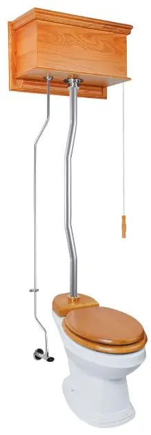
TOILET BOWL for “L” Pipe High Tank Toilet
 7 STEPS
INSTALLATION PROCEDURE
PLEASE READ BEFORE INSTALLING HIGH TANK TOILET
Preparation and Disassembly
-
Shut off water supply to existing toilet
-
Disconnect water supply tubing from existing tank and angle stop valve
-
Remove existing toilet and tank from floor
-
Remove old wax seal and clean area around the drain
-
Draw a line from the center of the drain to the wall.
Continue the line up the wall and draw a horizontal line at 60 inches. (this marks the molding bracket position).
NOTE: If not on a 15″ rough in, flush pipe (G) will need to be cut accordingly. Flush pipe (G) should be insterted in rear of bowl when being set.
Installation -
Turn toilet bowl upside-down. Place a new wax (remove any paper cover) ring and sleeve over drain horn. Press down firmly. (FIG 1)
-
Make sure toilet flange is clean and bolts point straight up. carefully position the toilet bowl over the flange and align the floor bolts with the holes in the toilet base. (FIG 2)
11. STEPS

| Part Letter | Part Description | QTY |
|---|---|---|
| A | Flush Arm | 1 |
| Al | Fill Valve | 1 |
| A2 | Flush Valve | 1 |
| A3 | Small Plastic Locknut (for Fill valve) | 1 |
| A4 | Large Plastic Locknut (for Flush valve) | 1 |
| AS | Rubber Fill Tube | 1 |
| A6 | Plastic Tank Liner | 1 |
| A7 | Wood Tank | 1 |
| B | Hanger Bracket | 2 |
| C | Pull Chain | 1 |
| D | Tank Mounting Lag Bolt | 1 |
| E | Coupler | 1 |
| G | 49″ Hard Flush Line | 1 |
| G1 | Donut Gasket (#22203) | 1 |
| J | Large Decorative Nut | 1 |
| K | Rubber Washer | 1 |
| L | ‘A” Dia. Hard Fill Line | 1 |
| N | Shut Off Valve | i |
| 0 | 12″ Flex Supply Line | 1 |
| P | Nipple | 1 |
| Q | Flange | 1 |
| S | S hook | 1 |
| S1 | Hook Screw (for Handle) | 1 |
| T | Bracket Screw | 2 |
| T2 | Molding Bracket Screw | 7 |
| T3 | WS Pin Head Screw | 6 |
| U | Bracket | 1 |
| V | Small Brass Decorative | |
| Nut | 1 | |
| W | Cone Washer | 1 |
| X | Cradle | 1 |
| Y | Handle | 1 |
| ZI. | Large Metal Locknut | 1 |
| Z2 | Large Rubber Gasket | 1 |
| Z3 | Small Rubber Gasket | 1 |
| Z5 | Plastic Slip Joint Washer | 2 |
| Z6 | Brass Slip Joint Nut | 1 |
| Z7 | Rubber Water Restrictor | 1 |
-
Install toilet as per manufacturers’ instructions. (Page 1)
-
Attach brass cradle (X) to front right side of wood tank (A?) using two SIS pinhead screws (T3). Make sure cradle is positioned over the inside of the tank. Using the Shook (S) attach the chain (C) to the right side of the flush arm (A).
Attach handle (Y) to chain. (FIG 1) -
Check and make sure the refill tube (A5) is inserted and securely connects the fill valve (A 1) to the flush valve (A2) . Insert Fill Valve (A 1) and Flush Vavle (A2) into tank liner (A6) and secure using provided plastic lock nuts (A3,A4 ).
(FIG 2) -
To mount moulding bracket (D), locate the centerline on the wall behind the bowl and mark tank height using instructions on page 1. We recommend that the bottom edge of the moulding bracket (D) be about 60 inches from the floor for a regular 16 inch toilet bowl. Secure moulding bracket (D) to studs with mounting screws (T2). If necessary, drill holes on the molding bracket (D), make sure not to drill within 1 inch of the perimeter. This area will be exposed. (FIG 3) If studs are not accessible, a wood backing can be installed between the studs. The backing must be installed behind the finished wall to provide a secure material to mount the moulding bracket (D).
-
Make sure rubber donut gasket (G1) (in rear port of toilet bowl) is fully seated. Push/twist bottom end of flush pipe (G) into donut gasket (G1) until pipe meets stop at far end of gasket (G1) and is fully seated in rear entry port of toilet bowl. (FIG 4)
-
Press down on the toilet bowl to compress and create a tight seal. Attach washers and nuts to floor bolts and tighten. (use adjustable, non-scratch wrench and do not over-tighten bolts). (FIG 4)
-
Align hanger brackets (B) on the wood tank to the inside notch of the molding bracket (D) and hang the wood tank (A?) onto molding bracket (D). (Fig 5)
-
Slide brass slip joint nut (Z6) followed by plastic joint washer (Z5) and large decorative nut (J) with rubber washer (K) into top end of flush tube (G). Inset rubber water restricter (Z7) inside flush tube (G) and loosely attach the large decorative nut (J) to the receiving thread of the flush valve (A2) on the wood tank. Slightly Tighten all joints. (FIG 6)
-
Install the nipple (P) to the water fitting from the wall.
Make sure to wrap both sides of the nipple (P) with thread sealer. Slide the flange (Q) onto the nipple (P) and install the shut off valve (N). (FIG 7) -
Slide the small decorative nut (V) from the opposite end of the fill line (L) (non collared end). Inset cone washer (W) between the fill line (L) and the small decorative nut (V) and loosely attach the small decorative nut (V) to the receiving thread of the fill valve (A 1 ). (FIG 9) Slide bracket (U) onto fill line (L) and secure to wall using provided screws (T). Use the coupler (E) to connect the 12 inch flex line (0) to the fill line (L) and attach to shut off valve (N). (FIG 10) Tighten all connections with a wrench and make sure all connections are squarely aligned to assure no leakage. Do a final check to make sure all connections are tight.
-
Turn off the shut off valve (N) and fill the tank to its waterline and test the flush system, checking for leaks. Water level is pre-adjusted from the factory and in some cases may need to be re-adjusted. CAUTION: Before turning on water please make sure all parts are secure and installed properly. Never use abrasives, detergent, or acids to clean the unit as they will damage the unit and void the warrenty.

SUPPLEMENTAL PART IMAGES

Read User Manual Online (PDF format)
Read User Manual Online (PDF format) >>