Sure-Lites AP2SQLED30 All Pro LED Emergency Light Instruction Manual
- June 17, 2024
- Sure-Lites
Table of Contents
Sure-Lites AP2SQLED30 All Pro LED Emergency Light

Product Information
Specifications:
- Model: IB50561122
- Brand: Sure-Lites
- Voltage Options: 120V, 277V
- LED Indicator: TEST LED indicator
Product Usage Instructions
J-Box Mounting Installation:
- Ensure AC power is turned OFF before starting installation.
- Remove the unit’s backplate by pushing through the two locking tabs at the bottom.
- The feed fixture leads through the backplate and connects to the AC power supply leads. Use Black & White wires for 120V and Red & White wires for 277V (refer to schematic).
Duct Mount Installation:
- Ensure AC power is turned OFF before starting installation.
- Remove the unit’s backplate by pushing through the two locking tabs at the bottom.
- Secure the backplate to the wall surface using keyhole knockouts.
- Remove the knockouts for conduit opening on the backplate and unit housing. Feed wires through the hole for conduit connection.
- For 120V, use Black & White wires and for 277V, use Red & White wires (refer to schematic).
- Complete the battery connection.
- Align tabs and push housing onto the backplate. Apply continuous AC power.
- After the battery has been charged for 24 hours, test the unit by pushing the test switch to turn on the LED lamp heads.
Operation:
The battery may not be fully charged initially. After connecting electricity
for at least 24 hours, normal operation should begin. Press the TEST button to
check if the LED lamps turn ON. Follow NFPA 101 guidelines for monthly and
annual testing of the emergency lighting system.
Note: UL recommends a maximum height of 16 feet for standard installation.
Frequently Asked Questions (FAQ):
-
Q: Can I install this product myself?
A: Installation and maintenance must be performed by a qualified electrician to ensure safety and proper functionality. -
Q: How often should I test the emergency lighting system?
A: The system should be tested monthly for at least 30 seconds and annually for 90 minutes as per NFPA 101 guidelines.
SAFETY WARNING
- Risk of Fire, Electrical Shock or other Casualty Hazards- Installation and maintenance of this product must be performed by a qualified electrician. This product must be installed by the applicable installation code by a person familiar with the construction and operation of the product and the hazards involved.
- Risk of Fire and Electric Shock- Make certain power is OFF before starting installation or attempting any maintenance. Disconnect power at the fuse or circuit breaker.
- Risk of Burn- Disconnect power and allow the fixture to cool before handling or servicing.
- Risk of Personal Injury- Due to sharp edges, handle with care.
DISCLAIMER OF LIABILITY: Cooper Lighting Solutions assumes no liability
for damages or losses of any kind that may arise from the improper, careless,
or negligent installation, handling or use of this product.
Note: Specifications and dimensions are subject to change without notice.
NOTICE: The fixture may become damaged and/or unstable if not installed
properly.
ATTENTION Receiving Department: Note the actual fixture description of
any shortage or noticeable damage on the delivery receipt. File claim for
common carrier (LTL) directly with the carrier. Claims for concealed damage
must be filed within 15 days of delivery. All damaged material, complete with
original packing must be retained.
Important Safeguards
READ AND FOLLOW ALL SAFETY INSTRUCTIONS SAVE THESE INSTRUCTIONS AND DELIVER TO
THE OWNER AFTER INSTALLATION
WARNING: RISK OF ELECTRIC SHOCK- NEVER CONNECT TO, DISCONNECT FROM, OR
SERVICE WHILE EQUIPMENT IS ENERGIZED.
WARNING: FAILURE TO FOLLOW THESE INSTRUCTIONS AND WARNINGS MAY RESULT IN
DEATH, SERIOUS INJURY OR SIGNIFICANT PROPERTY DAMAGE – For your protection,
read and follow these warnings and instructions carefully before installing or
maintaining this equipment. These instructions do not attempt to cover all
installation and maintenance situations.
READ AND FOLLOW ALL SAFETY INSTRUCTIONS
- All service shall be performed by a qualified service electrician. This product must be installed and maintained by the applicable installation codes by a person familiar with the construction & operation of the product and the hazards involved.
- This product must be installed by the applicable installation codes and ordinances.
- Before wiring to power supply, turn off electricity at fuse or circuit breaker.
- Disconnect AC power and unplug battery before servicing.
- Consult your local building code for approved wiring and installation.
- Do not let power supply cord touch hot surfaces.
- Do not mount near gas or electric heater.
- Equipment should be mounted in locations and at heights where it will not readily be subjected to tampering by unauthorized personnel.
- The use of accessory equipment not recommended by the manufacturer may cause an unsafe condition
- Do not use this equipment for other than intended use.
- Connect to an AC voltage as recommended on the product label of this equipment.
SAVE THESE INSTRUCTIONS.
Schematic:
Note: Unused input lead must be properly insulated with wire nut or other
approved method.
INSTALLATION INSTRUCTIONS
J-BOX MOUNTING INSTALLATION
- Before starting installation, make sure AC power is turned OFF.
- Remove unit’s backplate by pushing through the two locking tabs at the bottom using a narrow screwdriver.
- Feed fixture leads through the back plate and connect to AC power supply leads (Fig A). For 120V use Black & White wires and for 277V, use Red & White wires. (See Schematic.)

- Attach back plate to Junction Box [J-Box] (not provided) and secure with screws.
- Complete the battery connection. (Fig. B)

- Align tabs and push housing directly onto the backplate (Fig. C). Apply continuous AC power.
- After the battery has been left to charge for 24 hours, test the unit by pushing the test switch and the LED lamp heads will turn ON.

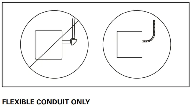
CONDUIT MOUNT INSTALLATION:
- Before starting installation, make sure AC power is turned OFF.
- Remove unit’s backplate by pushing through the two locking tabs at the bottom using a narrow screwdriver.
- Secure back plate to wall surface using keyhole knockouts.
- Remove the knockouts for conduit opening on the backplate and unit housing. Feed wires through the hole to make conduit connection. For 120V, use Black & White wires and for 277V, use Red and White wires (See Schematic).
- Complete the battery connection. (Fig. B)
- Align tabs and push housing directly onto the back plate (Fig. C). Apply continuous AC power.
- After the battery has been left to charge for 24 hours, test the unit by pushing the test switch and the LED lamps heads will turn ON.
OPERATION
The battery in this unit may not be fully charged when first installed. After
electricity is connected to the unit for at least 24 hours, then normal
operation of this unit should take effect. To check, press the “TEST” button.
The LED lamps on the unit should turn ON.
By NFPA 101, the emergency lighting system must be tested monthly for a
minimum of 30 seconds and annually for 90 minutes. Refer to the local codes
for any additional requirements that may apply.
Note: UL recommended maximum height is 16 Feet for standard.
Warranties and Limitations of Liability
Please refer to
www.cooperlighting.com/global/resources/legal
for our terms and conditions.
Cooper Lighting Solutions
1121 Highway 74 South
Peachtree City, GA 30269
P: 770-486-4800
www.cooperlighting.com
Canada Sales
5925 McLaughlin Road
Mississauga, Ontario L5R 1B8
P: 905-501-3000
F: 905-501-3172
© 2023 Cooper Lighting Solutions
All Rights Reserved
Publication No. IB50561122
June 20, 2023
049-336
Cooper Lighting Solutions is a registered trademark. All trademarks are property of their respective owners.
Product availability, specifications, and compliances are subject to change without notice
Read User Manual Online (PDF format)
Read User Manual Online (PDF format) >>