SENSOPART FT 25-RLHP Photoelectric Diffuse Sensor Instruction Manual
- June 15, 2024
- SENSOPART
Table of Contents
SENSOPART FT 25-RLHP Photoelectric Diffuse Sensor Instruction Manual

FT 25-RLHP
Photoelectric diffuse sensor
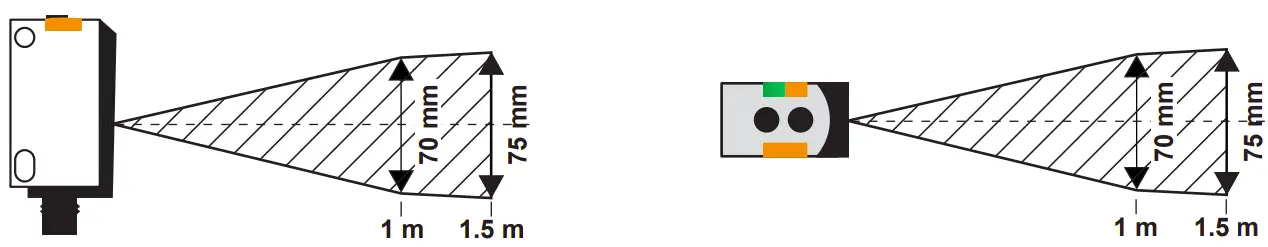
TECHNICAL DATA
| Switching output Q | Auto-Detect |
|---|---|
| Scanning distance (TW) 2) | 0 … 1500 mm |
| Used light | Laser, class 1 (IEC 60825-1) |
| Operating voltage +UB 3) | 18 … 30V DC |
| No-load supply current I0 | ≤ 60 mA |
| Output current Ie | ≤ 100 mA |
| Control input IN 4) | +UB= Teach-in |
-UB=
open = normal function
Factory setting| Single point = 1500 mm
- except for types Fx 25…-M3M/-M4M
- Reference material white, 90 % reflectance
- max. residual ripple 10 %, within UB, approx. 50 Hz/100 Hz
- see overview F; back
SAFETY INSTRUCTIONS
Read operating instructions before start-up.
Connection, assembly, setting and start-up only by trained personnel.
No safety component according to EU machinery directives (not suited for the
protection of personnel).
Not for outdoor use.
FT 25-RLHP-xxx: , class 1; wavelength: 658 nm; frequency: 100 kHz; pulse duration: 6 ns; limit value pulse: ≤ 0.65 mW (IEC 60825-1).
Complies with 21 CFR 1040.10 and 1040.11 except for deviations pursuant to laser Notice No. 56 dated May 2019.
For use with models with suffixes M3, M3M, M4, M4M,
KL4, KM4 : Straight or L-shaped M8 or M12 metal connector, connector base is
made of R/C (CYJV2).
CAUTION – Use of Controls or adjustments or performance of procedures other than those specified herein may result in hazardous radiation exposure
INTENDED USE
Sensor is used for the optical non-contact detection of objects.
ASSEMBLY
Fix sensor on suitable mounting component (see www.sensopart.com).
CONNECTION
- Insert plug voltage-free and screw it tightly.
- Connect cable according to the connection diagram (see illustration B) .
- Auto-Detect: Simply connect the sensor. The switching load NPN or PNP will be detected automatically (manually see Illustration J). Important: Load voltage and supply voltage are from the same source. A parallelswitching of the sensors is not possible with Auto-Detect.
- For PNP/NPN/Auto-Detect see illustration C.
- Apply voltage → green LED lights up.
- Switching N.O. ↔ N.C. (see illustration I; back).
- N.O. = normally open; N.C. = normally closed.
- IO-Link Communication → green LED flashes.
ADJUSTMENT (SEE ILLUSTRATION D)
Align sensor to the target object. Observe the preferential direction of proximity switches.
DIMENSIONAL DRAWING
- Yellow LED1)
- Button
- Green LED 2)
- Receiver axis
- Emitter axis
switching output indicator afficheur sortie de commutation
operating voltage indicator afficheur tension de service

FT 25-RLHP
- A 7.3
- B 11.2
SWITCHING MODE

CONNECTION

ADJUSTMENT

Prevention of further light spots in the hatched area
SETTING
The sensor has 3 differerent Teach-in modes.
Standard Teach-in (STI): is suited for nearly all applications. Setting is made on object and background (see illustration G).
Object-Object Teach-in (OTI): is suited for applications where the background cannot be taught in. Setting is made 2x on the object. (see illustration H).
Dynamic Teach-in (DTI): is suited for setting the sensor in the running process, particularly for small objects (see illustration I).
MAINTENANCE
SENSOPART sensors are maintenance-free. We recommend to cyclically clean the
optical surfaces and check the screw connections and plug connections.
FACTORY SETTING

STANDARD TEACH-IN (STI)
Step 1: Teach-in object

Step 2: Teach-in background
DYNAMIC TEACH-IN (DTI)
Step 1: During running process

Step 2: Teach-in object during running process

External Teach-in → F
OBJECT-OBJECT TEACH-IN (OTI)
Step 1: Teach-in object

Step 2: Teach-in object
SWITCHING N.O. / N.C

SETTING MODES

SWITCHING AUTO-DETECT / NPN / PNP

SWITCHING FREQUENCY

IMPORTANT
If green & yellow LED flash alternately:
Other switching frequency was set via IO-Link.
www.sensopart.com Änderungen vorbehalten | subject to change | sous réserve de modifications | salvo modificación

References
Read User Manual Online (PDF format)
Read User Manual Online (PDF format) >>