Shenzhen Ruiyi GM3-DZ Smart Fingerprint Door Lock Password Electronic User Manual
- June 10, 2024
- Shenzhen Ruiyi
Table of Contents
Shenzhen Ruiyi GM3-DZ Smart Fingerprint Door Lock Password Electronic
Product Information
Specifications
- Model: XYZ-2000
- Power: 1200W
- Capacity: 1.5 liters
- Material: Stainless steel
- Dimensions: 10 x 12 x 8 inches
- Weight: 5 lbs
Product Usage Instructions
- Before using the XYZ-2000, ensure that all packaging materials are removed and the product is placed on a flat, stable surface.
- Open the lid of the kettle and fill it with water up to the desired level, making sure not to exceed the maximum capacity of 1.5 litres.
- Connect the kettle to a power source and press the power button to start heating the water.
- The XYZ-2000 features adjustable temperature settings. Use the control panel to set the desired temperature for your hot water.
- Once the water reaches the set temperature, carefully pour it out using the spout and serve as needed.
FAQ
- Q: Can I heat beverages other than water in the XYZ-2000?
- A: The XYZ-2000 is designed specifically for heating water. Do not use it to heat any other beverages.
- Q: How do I clean the kettle?
- A: To clean the kettle, unplug it and allow it to cool down. Wipe the exterior with a damp cloth and use a mild detergent to clean the interior. Rinse thoroughly before use.
- Q: Is the XYZ-2000 dishwasher safe?
- A: No, do not place any part of the XYZ-2000 in a dishwasher. Hand wash only.
GM3 Series User Manual
-
If the product has Bluetooth function, please be sure to download the TT-lock app and bundle it with the mobile phone administrator.
-
Be sure to insert the square bar into the front handle to the end, and then adjust the clutch according to the instructions in the manual before opening and closing the lock normally.
-
The mechanical key can only be twisted after the product is installed and can be used normally to avoid damage to the clutch.
-
The USB charging port needs to be plugged and unplugged lightly, and the power bank cannot be hung to charge, to avoid the USB charging port falling off and breaking due to gravity.
If the USB charging port falls off and breaks, it is not covered by the free warranty. -
Please choose the corresponding installation instructions according to the purchased product and compare the installation:

OPERATION MANUAL

Parameters
- Model: GM3-DZ
- Cover: D70mm / Lever: L150mm / Height:62mm
- Material: Aluminum alloy+Acrylic
- Available Thickness: 35mm ~ 55mm
- Unlock Way: Key/Fingerprint
- Power Supply: 4 x AAA Alkaline Batteries
- Emergency Supply: USB(Type-C Interface)
- Working Voltage: 6V
- Alarm Voltage: 4.8V
- Capacity: Fingerprint——30sets
Parts list

Overall

- Front Handle
- Emergency power supply
- Front Cover
- Hollow Square Bar
- Screw Bolt
- Key
- Data Line
- Spring
- Back Cover
- Back Handle
- Screw
- Battery Cover
- Battery Box
- Data Line Interface
- Setting Button
Installation
- Drill holes in the door and install the lock body according to the drawings
- Install the two screw bolts on the front cover, Insert the hollow square bar into the bottom of the front lever and let the data line stick out

- Rotate the bar to the bottom towards the handle direction.
- Then rotate back 90° to complete the positioning

- Then rotate back 90° to complete the positioning
- Insert the exterior assembly into the doorhole
- Install the interior assembly on the door. Make sure the connection wire goes through the spring and the back handle. (Notice: The spring is not necessary when the door’s thickness does not exceed 45MM)
- Tighten the door lock with two screws and connect the data cable

- Install om alkaline batteries and the battery
- As shown in the picture, press down to open the battery cover

GM3-DZML OPERATION MANUAL

Parameters
- Model: GM3-DZML
- Cover: D70mm / Lever: L150mm / Height:62mm
- Material: Aluminum alloy + Acrylic
- Available Thickness: 35mm ~ 55mm
- Unlock Way: Key /Fingerprint/password/Tuya APP
- Power Supply: 4 x AAA Alkaline Batteries
- Emergency Supply: USB(Type-C Interface)
- Working Voltage: 6V
- Alarm Voltage: 4.8V
- Capacity:
- Fingerprint——50sets
- Password——100sets
Parts list

Overall

- Front Handle
- Emergency power supply
- Front Cover
- Hollow Square Bar
- Screw Bolt
- Key
- Data Line
- Spring
- Back Cover
- Back Handle
- Screw
- Battery Cover
- Battery Box
- Data Line Interface
- Setting Button
Installation
- Drill holes in the door and install the lock body according to the drawings
- Install the two screw bolts on the front cover, Insert the hollow square bar into the bottom of the front lever and let the data line stick out

- Rotate the bar to the bottom towards the handle direction.
- Then rotate back 90° to complete the positioning
- Insert the exterior assembly into the doorhole

- Install the interior assembly on the door. Make sure the connection wire goes through the spring and the back handle. (Notice: The spring is not necessary when the door’s thickness does not exceed 45MM)
- Tighten the door lock with two screws and connect the data cable

- Install 4 AAA alkaline batteries and the battery cover to complete the installation
- As shown in the picture, press down to open the battery cover

GM3-FZ/ GM5-FZ OPERATION MANUAL

Parameters
- Model: GM3-FZ / GM5-FZ
- Cover: D70mm / Lever: L150mm / Higt:62mm
- Material: Aluminum alloy + Acrylic
- Available Thickness: 35mm ~ 55mm
- Unlock Way: Key/Fingerprint
- Power Supply: 4 x AAA Alkaline Batteries
- Emergency Supply: USB(Type-C Interface)
- Working Voltage: 6V
- Alarm Voltage: 4.8V
- Capacity: Fingerprint——30sets
Parts list

Overall

-
Front Handle
-
Emergency power supply
-
Front Cover
-
Front Cylinder hole Cover
-
Screw Bolt
-
Hollow Square Bar
-
Data Line
-
Spring
Non-essential accessories, please select according to the thickness of the door -
Back Cylinder hole Cover
-
Back Handle
-
Screw
-
Cylinder
-
Battery Box
Some models of products do not include this accessory -
Data Line Interface
-
Setting Button
Installation
-
Drill holes in the door and install the lock body according to the drawings
-
Install the studs on the front cover and keyhole front cover, and put the hollow. The square tube is inserted through the connecting wire into the bottom of the front handle

-
Take the illustration as an example, rotate the square tube counterclockwise to the end.
- (If the door is left open, turn it clockwise to the end)
-
Insert the front lever into the doorhole

-
Install the back handle on the door, making sure the connection wire goes through the spring and the back handle. The door thickness does not exceed 45mm without adding springs
-
Fix the lock cylinder, handle and escutcheon with screws, and connect the wire ends.
The sub is fixed on the setting button board.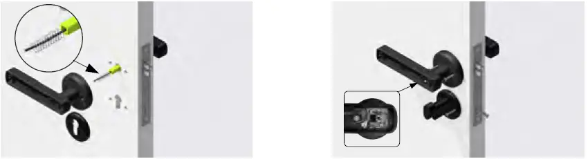
-
Insell complete stories and the battery
-
As shown in the picture, The installation is complete

GM3-FZ/ GM5-FZ OPERATION MANUAL

Parameters
- Model: GM3-FZML / GM5-FZML
- Cover: D70mm / Lever: L150mm / Higt:62mm
- Material: Aluminum alloy+ Acrylic
- Available Thickness: 35mm ~ 55mm
- Unlock Way: Key/Fingerprint
- Power Supply: 4 x AAA Alkaline Batteries
- Emergency Supply: USB (Type-C Interface)
- Working Voltage: 6V
- Alarm Voltage: 4.8V
- Capacity: Fingerprint ——30sets
Parts list

Overall

-
Front Handle
-
Emergency power supply
-
Front Cover
-
Front Cylinder hole Cover
-
Screw Bolt
-
Hollow Square Bar
-
Data Line
-
Spring
Non-essential accessories, please select it according to the thickness of the door -
Back Cylinder hole Cover
-
Back Handle
-
Screw
-
Cylinder
-
Battery Box
Some models of products do not include this accessory -
Data Line Interface
-
Setting Button
Installation
-
Drill holes in the door and install the lock body according to the drawings
-
Install the studs on the front cover and keyhole front cover, and put the hollow. The square tube is inserted through the connecting wire into the bottom ofthe front handle

-
Take the illustration as an example, rotate the square tube counterclockwise to the end.
(If the door is left open, turn it clockwise to the end) -
Insert the front lever into the doorhole

-
Install the back handle on the door, making sure the connection wire goes through the spring and the back handle. The door thickness does not exceed 45mm without adding springs
-
Fix the lock cylinder, handle and escutcheon with screws, and connect the wire ends.
The sub is fixed on the setting button board.
-
Install 4 AAA alkaline batteries and the battery cover to complete the installation
-
As shown in the picture, The installation is complete

E.Set up(Fingerprint+Key)
Administrator fingerprint settings
(The first 3 fingerprints are administrators)
- Long press the fingerprint for 5 seconds until the green light flashes and then release your finger (the green light flashes to indicate that the first entry can be started)
- Repeatedly press the fingerprint with your finger 5 times (the blue light flashes once for each press, and the fifth time the green light flashes for 1.5 seconds and there is a long beep)
- Enter successfully
Note: press 5 seconds—–press 5 times—–and succeed
User fingerprint setting
- Press and hold the fingerprint for 5 seconds until the green light is on and then release your finger (the green light is on to indicate that the administrator can be verified)
- Verify the administrator’s fingerprint successfully, the green light will flash and there will be a beep (you can start recording if the verification is successful)
- Repeatedly press the fingerprint with your finger 5 times (the blue light flashes once for each press, and the fifth time the green light flashes for 1.5s and there is a long beep)
- Enter successfully
Note: press 5 seconds—–press 1 time—-press 5 times—–success
Restore factory settings
- Long press the setting button for 13 seconds until the red light is on
- Let go within 3 seconds when the red light is on, and the factory settings are restored successfully (timeout to exit the operation)
Unlock mode setting
(In unlocked mode, you can directly turn the handle to open the door without
fingerprint verification) Method one
- Press and hold the setting key for 1 second and release to enter the normally open mode
- Repeat the above operation to return to the normal locking mode
Method one
- Press and hold the setting key for 1 second and release to enter the normally open mode
- Repeat the above operation to return to the normal locking mode
Method Two
- Press and hold the fingerprint for 10s until the blue light turns on, then release your finger
- After verifying the administrator’s fingerprint successfully, the green light is on, and it enters the unlock mode
- Match the fingerprint of the administrator to return to the normal lock mode
Lighting description
- Successful entry: green light, 1 beep
- Entry failure: red light flashes 2 times, beeps 2 times
- Successful fingerprint acquisition: blue light flashes 1 time, beeps 1 time
- Fingerprint collection failed: red light flashes 1 time, beeps 2 times
- Administrator verification failed: red light flashes 2 times, beeps 2 times
- Fingerprint registration is successful: the blue light is always on for 1.5s, and there is a long beep
- Fingerprint deletion failed: red light flashes 1 time, beeps 2 times
- Low battery warning: red light flashes for 5s (10 flashes), beeps 10 times
- Charging: the red light is always on
- Fully charged: the green light is always on
- Successful unlocking: the green light flashes once and beeps once
- Reset successful: the blue light flashes once and beeps once
Lock function setting
F.Lock function setting(Fingerprint+Password+APP Bluetooth+Key)
- Administrator information: refers to the fingerprint and password of the administrator.
- Unlock information: refers to the entered fingerprints and passwords (including administrators and ordinary users)
- The “#” key has two modes:
- A. It is the confirmation key or the function key for entering the menu;
- B. The clear key/back key (click to clear when entering the password).
- The operating system will automatically exit if there is no operation for more than 20 seconds.
- After the voltage is lower than 4.8V, it will prompt “low battery, please replace the battery” every time you unlock, please replace the battery in time.
- In normal open mode, click the setting button, and the voice prompts “normal open mode” and “normal open has been canceled and locked”
Factory default state
- The factory administrator’s initial password is “123456”. In the initial state, any fingerprint can unlock the lock.
- After entering the administrator information, the lock cannot be unlocked without entering the fingerprint and password
Door lock function management

Menu list

APP settings
Reminder: The product is a Tuya Bluetooth lock, the administrator of the APP
is the ultimate administrator of the lock, and the operation function of the
lock end is an auxiliary operation, please be sure to download the Smart Life
APP to bind the administrator, unless it can be ensured that the lock will not
be used by unrelated people APP is bundled.
-
Download and install the “Smart Life” APP from the application market.
Remarks: Users can also download the “Tuya Smart” APP, and the setting and usage methods are the same. -
After the installation is complete, follow the prompts to register and log in.
Users can also download and install the APP by scanning the QR code below:

Register an account and add devices

Improve family information

Fingerprint and password enroll
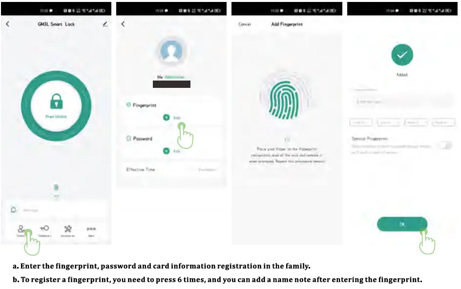
Fingerprint and password enroll
Delete fingerprints and passwords

One-time password

Log
More
- Automatic locking: Normally open mode switch;
- Door lock volume: Mute setting, lock end entering menu will broadcast voice;
- Door lock language: Switch between Chinese and English.
Unbind

FCC STATEMENT
FCC WARNING
This device complies with part 15 of the FCC Rules. Operation is subject to the following two conditions:
- this device may not cause harmful interference, and
- this device must accept any interference received, including interference that may cause undesired operation.
Any changes or modifications not expressly approved by the party responsible for compliance could void the user’s authority to operate the equipment.
NOTE: This equipment has been tested and found to comply with the limits for a Class B digital device, pursuant to Part 15 of the FCC Rules.
These limits are designed to provide reasonable protection against harmful interference in a residential installation. This equipment generates, uses and can radiate radio frequency energy and, if not installed and used in accordance with the instructions, may cause harmful interference to radio communications. However, there is no guarantee that interference will not occur in a particular installation. If this equipment does cause harmful interference to radio or television reception, which can be determined by turning the equipment off and on, the user is encouraged to try to correct the interference by one or more of the following measures:
- Reorient or relocate the receiving antenna.
- Increase the separation between the equipment and receiver.
- Connect the equipment into an outlet on a circuit different from that to which the receiver is connected.
- Consult the dealer or an experienced radio/TV technician for help.
To maintain compliance with FCC’s RF Exposure guidelines, This equipment should be installed and operated with minimum 20cm distance between the radiator and your body: Use only the supplied antenna.
Read User Manual Online (PDF format)
Read User Manual Online (PDF format) >>