ConcealFab 901124 Front Absorber Kit Instruction Manual
- June 1, 2024
- ConcealFab
Table of Contents
- PARTS
- PRECAUTIONS
- INTRODUCTION
- PROCEDURE FOR ASSEMBLING FRONT ABSORBER KIT (901124)
- RECOMMENDED TEST PROCESS
- PROCEDURE FOR INSTALLING ABSORBER SYSTEM
- PERFORMANCE CONSIDERATIONS
- POWER HANDLING
- PRODUCT CARE / HANDLING
- CUSTOMER SUPPORT
- Read User Manual Online (PDF format)
- Download This Manual (PDF format)
ConcealFab 901124 Front Absorber Kit

PARTS
| Front Absorber Kit | Part No. 901124 |
|---|---|
| Rear Absorber Kit | Part No. 901125 (2-inch thick) |
Part No. 901162 (1-inch thick)
Side PIM Blanket| Part No. 007640-2400008

PRECAUTIONS
WARNING: Front and Rear Absorber Kits contain carbon coated polyurethane foam, which can ignite if exposed to high RF power for prolonged periods of time. Once ignited, polyurethane foam can melt forming a combustible liquid that will burn rapidly, generate dense smoke, and generate toxic gases that could be fatal if inhaled in sufficient quantities.
WARNING: Do not exceed safe thermal limits described in Section 7 of this guide.
WARNING: Allow Front Absorber Kit pads to cool between tests. Allow the pads to cool for a period of time greater than the test duration after each use. (No cooling between tests is required for Rear Absorber Kit pads when installed behind an antenna or for Side PIM Blankets installed on the sides of an antenna.)
WARNING: Do not install Rear Absorber Kit pads on the front face of site antennas. Rear Absorber Kit pads installed directly on the front face of site antennas can get hot and damage the antenna radome. Only install Front Absorber Kit pads on the front face of site antennas.
WARNING: Do not use the Absorber Kit System in winds exceeding 15 mph.
INTRODUCTION
Passive Intermodulation (PIM) sources located beyond an antenna, referred to as “external” PIM sources, can be a challenge to locate. PIM analyzers typically include a Distance-to-PIM (DTP) function that is very useful in aiding PIM hunts. Unfortunately, these measurements only identify how far the PIM source is from the antenna with no indication of direction. When the distance indicated by a PIM analyzer is less than 15 FT (4.5 m), experience has shown that the PIM source can be located directly behind or beside the antenna. As a result, guesswork is required to determine where to begin the PIM hunt.
CPRI analyzers can also be used to aid PIM hunts. These analyzers tap into the optical connection between the Base Band Unit (BBU) and a Remote Radio Unit (RRU) and allow the user to view the uplink spectrum for each branch. When the highest magnitude PIM source is covered with a PIM blanket or is repaired, the average uplink noise level will reduce. Without a Distance-to-PIM function to aid the hunt, test technicians using a CPRI analyzer must rely completely on intuition to determine where to start hunting.
ConcealFab’s Absorber Kit System is an additional tool that can be used during a PIM hunt to help determine PIM source direction when using a PIM analyzer or when using a CPRI analyzer to measure progress. If the PIM magnitude or uplink noise level reduces when the Front Absorber Kit (901124) is installed on the front of an antenna, the PIM source is likely in front of the antenna. If the PIM magnitude or uplink noise level does not reduce (or increases) when the Front Absorber Kit is installed on the front of the antenna, the PIM source is likely behind or beside the site antenna. ConcealFab’s Rear Absorber Kits (901125 or 901162) and Side PIM Blanket (007640 2400008) complete the Absorber Kit System and can be used with the Front Absorber Kit to refine PIM source direction. (See recommended test flow chart in Section 4).
In addition to PIM Hunting, ConcealFab’s Absorber Kit System can be used while site testing to help isolate the antenna and its feed system from the environment. If the PIM magnitude or uplink noise level decreases when the complete Absorber Kit System is installed on the antenna, it is a good indication that the largest noise source is beyond the antenna. If the PIM magnitude or uplink noise level does not change or increases when the complete Absorber Kit System is installed, it is a good indication that the largest noise source is inside the antenna or its feed system.
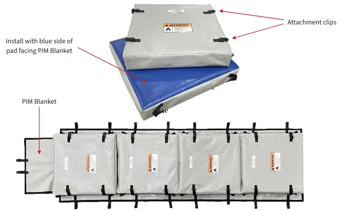
PROCEDURE FOR ASSEMBLING FRONT ABSORBER KIT (901124)
-
Lay the Front Absorber Kit blanket on a flat surface with clips facing up
-
Select the number of absorber pads required to completely cover the front of the antenna
-
Place the pads on the PIM Blanket with the blue side facing the blanket (side without clips)
-
Secure each pad to the blanket using the 4 plastic attachment clips
-
Synch pads together to prevent gaps > ½-inch (1.3 cm) using non-metallic fasteners such as Nylon Zip-ties, Velcro straps, cord, etc.

-
Fold excess blanket length up and secure to back of PIM blanket using Velcro strips
-
Install three bungee cords through loops in blanket (top, bottom and close to center) cord, etc.
-
Front Side

-
Back Side

-
RECOMMENDED TEST PROCESS
The flow chart below provides the recommended process for using the Absorber
Kit System to determine PIM / noise source direction. While monitoring the PIM
/ uplink noise level, install the full Absorber Kit System in accordance with
the instructions in Section 5. If high PIM / uplink noise persists with the
full Absorber Kit System installed, the largest PIM / noise source is likely
inside the antenna feed system. Systematically removing the individual
components of the Absorber Kit System while monitoring PIM / uplink noise will
guide the user to the direction of the largest PIM / noise source.

PROCEDURE FOR INSTALLING ABSORBER SYSTEM
Install the Side PIM blanket:
-
Drape the Side PIM Blanket over the top of the antenna with equal halves hanging down each side of the antenna.

-
Secure the Side PIM Blanket to the mast using the two sewn loops in the center of the Blanket.
Install the Front Absorber Kit:
- Place the Front Absorber Kit in front of the directional panel antenna with the pads facing the antenna.
- Pull the upper flap tight against the top of the antenna and secure to the mast or upper antenna mounting brackets using the sewn Nylon loops in the PIM Blanket and the provided Nylon strap.
- Pull the Front Absorber Kit flush with the antenna surface using the bungee cords provided.
- Push the absorber pads up and tighten the mounting strap and bungee cords to prevent a gap >6 inches (15 cm) at the top of the antenna.

Install the Rear Absorber Kit pads:
- Slide Rear absorber kit pads between the antenna mounting mast and the antenna.
- Cover as much rear area of the antenna as possible.
- Different sized pads are provided in the kit to account for different antenna bracket spacing.

Pads of different sizes included with each Rear Absorber Kit
PERFORMANCE CONSIDERATIONS
For the Absorber System to work correctly its components must not generate significant PIM when attached to the antenna. The Front Absorber Kit (including the bungee cords used to secure the kit to the antenna) and Side PIM Blanket require very stringent PIM ratings due to the higher RF signal levels they see when installed. The Rear Absorber Kit does not require as stringent a PIM rating due to the reduced RF signal level experienced when installed behind directional antennas.
CAUTION: Do not place Rear Absorber Kits closer than 1 wavelength to the front or to the side of directional base station antennas. PIM generated by the Rear Absorber Kits when placed too close to the front or side of a base station antenna can provide false noise / PIM readings.
A second requirement for the Absorber Kit System is that it should have minimum impact on the Voltage Standing Wave Ratio (VSWR) of the antenna system. A high impedance mismatch will occur when RF absorbing foam is placed directly on the front face of an antenna. ConcealFab’s Front Absorber Kit pads include specially engineered RF absorbing foam spaced away from the antenna surface by a polyurethane foam spacer to minimize impedance mismatches. When ConcealFab’s Front Absorber Kit is installed on the front face of a directional panel antenna, the VSWR typically does not degrade below 1.92:1 (10 dB Return Loss).
CAUTION: The Front Absorber Kit must be assembled and installed correctly to prevent false noise / PIM readings. The blue side of each Front Absorber Kit pad (side without plastic clips) must face the PIM blanket. When the Front Absorber Kit is attached to the antenna, the absorber pads (not the PIM blanket) must face the antenna.
Due to mechanical tolerances, it is possible for absorber pads to have open spaces between pads after attachment to the blanket. High RF reflection can occur at these gaps that can cause false PIM / noise readings. Nylon loops are provided on the sides of the Front Absorber Kit pads providing locations to synch pads together using Nylon Zip-ties to eliminate gaps.
CAUTION: Push Front Absorber Kit pads together after installing on the antenna to eliminate gaps greater than ½-inch (1.3 cm). If gaps persist, close gaps by synching pads together using Nylon Zip-ties. Tests have shown that a PIM blanket installed on the side of a directional panel antenna has minimal impact on VSWR. For this reason, ConcealFab developed the Side PIM Blanket as a component of the Absorber Kit System rather than creating side absorber pads. The Side PIM Blanket is low PIM, provides very high RF attenuation, is less expensive than RF absorber material and is easier to handle and secure than multiple narrow side absorber pads.
CAUTION: The Side PIM Blanket should only cover the sides of a base station panel antenna and not be placed in front of the antenna. Placing a PIM blanket in front of or wrapping an antenna with a PIM Blanket will reflect significant RF energy back into the antenna and the radio that can cause damage and can provide false noise / PIM readings.
POWER HANDLING
RF energy absorbed by the Front and Rear Absorber Kit pads is converted to heat, similar to the way that a microwave oven heats food. It is very important to limit the total RF power and test duration to prevent Front Absorber pads from over-heating. See charts below for guidance on safe test durations for typical directional panel antennas of various lengths and azimuth beamwidths.
RF heating is not uniform in the Front Absorber Kit pads. Hot spots occur in the absorber material where RF energy from multiple radiating elements inside the antenna phase together to focus the antenna beam.
Observations related RF heating are:
- Heating increases as the antenna horizonal half-power beam with decreases
- Heating increases as the antenna height decreases (energy concentrated into fewer pads) The safe test guidance charts provided in this section were determined experimentally by installing thermocouples inside Front Absorber Kit pads installed on directional panel antennas while transmitting high power modulated RF signals in the 600 MHz, 700 MHz, 1900 MHz, and 2100 MHz frequency band. The recommended safe thermal limit of 350°F corresponds to the temperature identified on the polyurethane foam SDS where generation of irritating odors is possible. ConcealFab has heated the polyurethane foam to well over 400°F for short periods of time during our tests with no evidence of physical damage, indicating that the recommended safe thermal limit is conservative. The recommended safe thermal limit is well below the autoignition temperature of polyurethane foam (698°F).
Allow Front Absorber Kit pads to cool between tests. Allow the pads to cool for a period of time greater than the test duration after each use.
CAUTION: The power level shown in the charts below is the total RF power transmitting from the antenna, including artificial loading using AILG / OCNS and actual traffic loading. Do not assume there is zero RF power transmitting in bands that are not artificially loaded! Lock all bands not considered in the power level calculation to prevent overheating.
For antenna / power configurations not represented by a table below, the following formula can be used to determine a safe test duration.
Tmax = (50 – ((PA – 330) / 3.5)) (BWA / 65) + (((HA – 4) / 4) 10)
Where:
- Tmax = Maximum recommended test time (minutes)
- PA = Actual total power transmitting into Front Absorber (Watts)
- BWA = Actual antenna horizontal half-power beamwidth (Degrees)
- HA = Actual antenna height (Feet)
CAUTION: The above formula should not be used for antennas with stacked arrays. (Short, lower gain arrays stacked on top of each other to achieve higher port count.) The formula assumes that the length of each antenna array extends a minimum of 75% of the antenna height (spreading the RF power over a larger area). If in doubt, check with the antenna manufacturer.
Safe test durations for common antenna configurations:


Safe test durations for common antenna configurations (continued):


PRODUCT CARE / HANDLING
-
The components of the Absorber Kit System are covered with Vinyl coated polyester scrim material that is both UV and Mildew resistant. This durable fabric is designed to protect the Absorber Kit System components from normal wear and abrasion.
-
Do not step on or crush the Absorber Kit System pads.
-
Do not expose any component of the Absorber Kit System to an open flame.
-
If torn, patch tears using commercially available Vinyl fabric repair tape.
-
The Vinyl fabric is water resistant and able to protect the Absorber Kit System components from light precipitation. Avoid long term exposure to heavy rain. Wipe the Absorber Kit System components dry before storing.
-
The Vinyl fabric can be cleaned using water and a mild detergent.
-
ConcealFab offers a soft transit bag for transporting, storing, and hoisting the Absorber Kit System. Two transit bags (2x PN 901230) are required to transport one complete Absorber Kit System (Front Absorber Kit, Rear Absorber Kit, and Side PIM Blanket).
-
Aborber Kit transit bag, PN 901230 (Sold Separately)

-
Two Absorber Kit transit bags required to transport complete Absorber Kit System
-
CUSTOMER SUPPORT
10205 Federal Drive, Building B • Colorado Springs, CO 80908
+1 719.599.3400
www.concealfab.com
Updated: December 21, 2022
Read User Manual Online (PDF format)
Read User Manual Online (PDF format) >>