KSD2853 Antenna Module User Manual
- May 15, 2024
- KSD
Table of Contents
- Features
- Application Diagram
- Specifications
- Electrical Characteristics
- AUDIO Features
- RF Characteristics
- Module Pin definitions
- Pin Configurations
- Module Package Information
- Power on sequence
- Recommended keep out area information
- PCB antenna radiation pattern
- Soldering recommendations
- Read User Manual Online (PDF format)
- Download This Manual (PDF format)
KSD2853 Antenna Module User Manual

Features
- 32bit RISC processor Core, up to240MHz
- Internal 203KB RAM for data and program storage
- Internal 2MByte Nor flash
- Support 24MHz OSC with on-chip PLL
- Internal 32KHz RC oscillator
- 8-channel ordinary DMA, support for transmission in burst 8 mode
- Support Bluetooth V5.3, compatible with Bluetooth V5.0/4.2/4.2 LE/4.0/2.1 + EDR system
- Compatible with AVRCP Profile V1.6.2
- Compatible with A2DP Profile V1.3.2
- Compatible with HFP Profile V1.8
- Built-in stereo 24bit sigma-delta DAC
- DAC supports sample rate of 8k/11.025k /12k/16k/22.05k/24k/32k/44.1k/48k/88.2k/96 kHz
- Built-in stereo 20mW PA for headphone
- Built-in stereo 24bit sigma-delta ADC
- ADC supports sample rate of 8k/11.025k /12k/16k/22.05k/24k/32k/44.1k/48k/88.2k/96 kHz
- Support 3 pairs input 0/1/2; each pair can be formed as mix or differential input.
- Support 2 DMIC input
- I2S TX&RX support master and slave mode separately, and support sample rate of 192k/96k/48k/44.1k/32k/24k/22.05k/16k/12k/11.025k/8k
- Support SPDIF TX , SPDIF RX and CEC
- Rich Interfaces support: SD,MMC/eMMC,USB2.0FS, 2xUART, 2xTWI, 1xSPI, IR RX, 9xPWM, support LCD with 8bit CPU interface, 1/3Bias, 3COM、4 COM , maximum 9SEG SEG_LCD Driver,7/8pin LED
- 24 Programmable GPIOs, and 10 analog IOs can also configure as GPIOs.
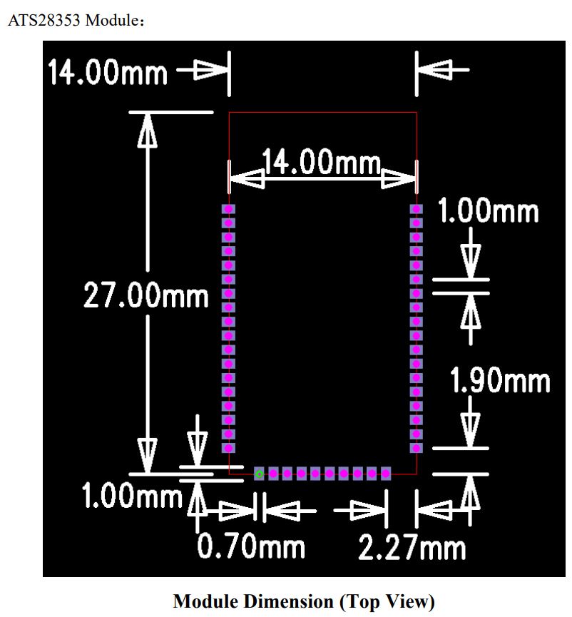
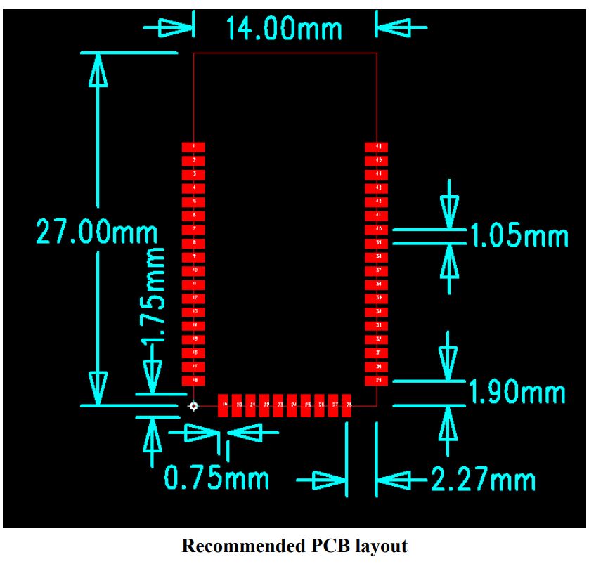
- PCB Dimension:
- L27×W14×H2.5 ±0.1 mm
ATS2853 BT Module With ANT
Bluetooth Audio Solution
Wireless Audio Applications MMC/SD Card Audio Playback
Bluetooth car audio unit Sound Bar
Bluetooth V5.3
Applications
- Wireless Audio Application
- MMC/SD Card Audio Playback
- Bluetooth car audio unit
- Sound Bar
Application Diagram
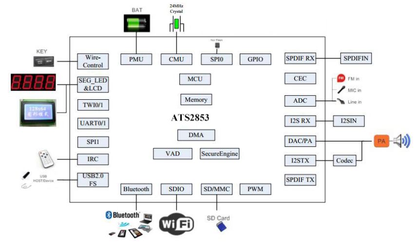
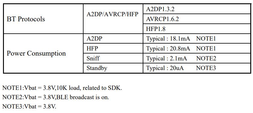
Specifications

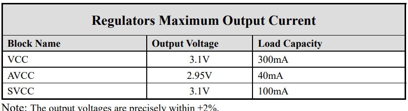
Electrical Characteristics

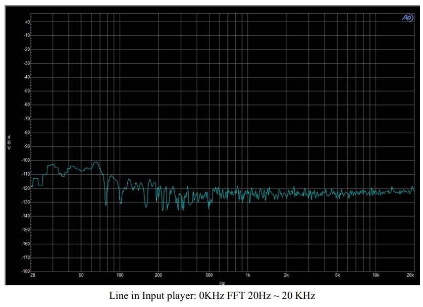
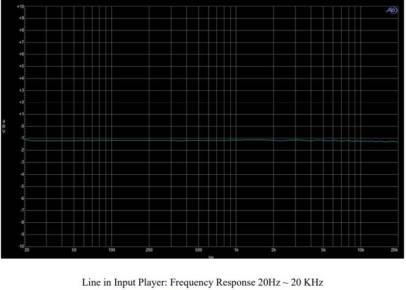
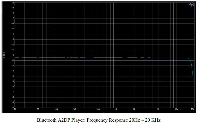
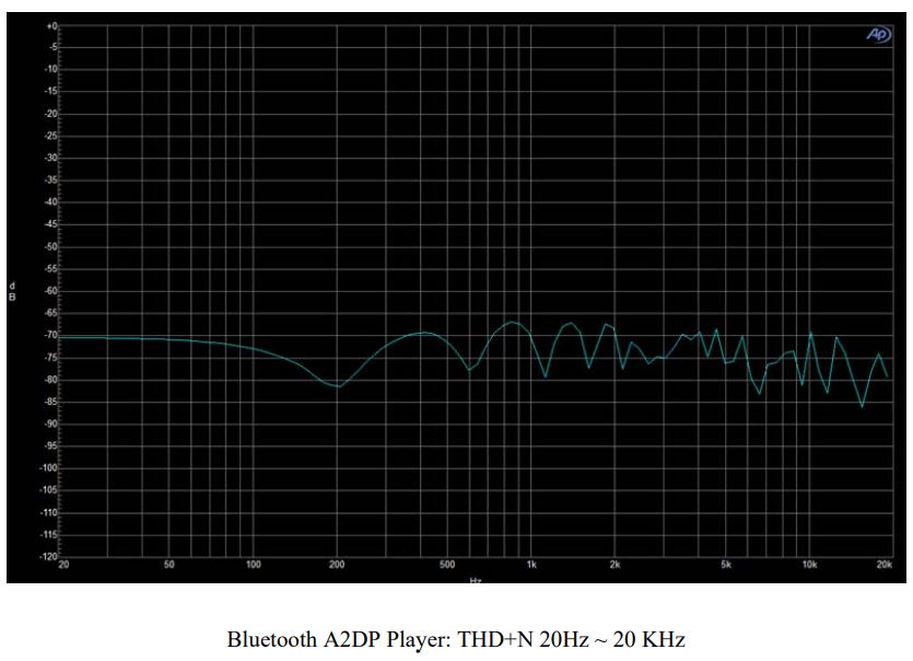
AUDIO Features
Test Condition: Power BAT=3.8V, Analog audio output AOUTL/R, Load = 10K ohm,
BW=20Hz ~ 20 KHz, Test equipment: AP2722.
DAC/ADC audio output performance chart:
Line in Input Mode:

Bluetooth Player Music Mode:

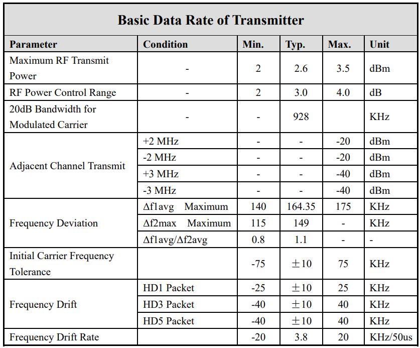
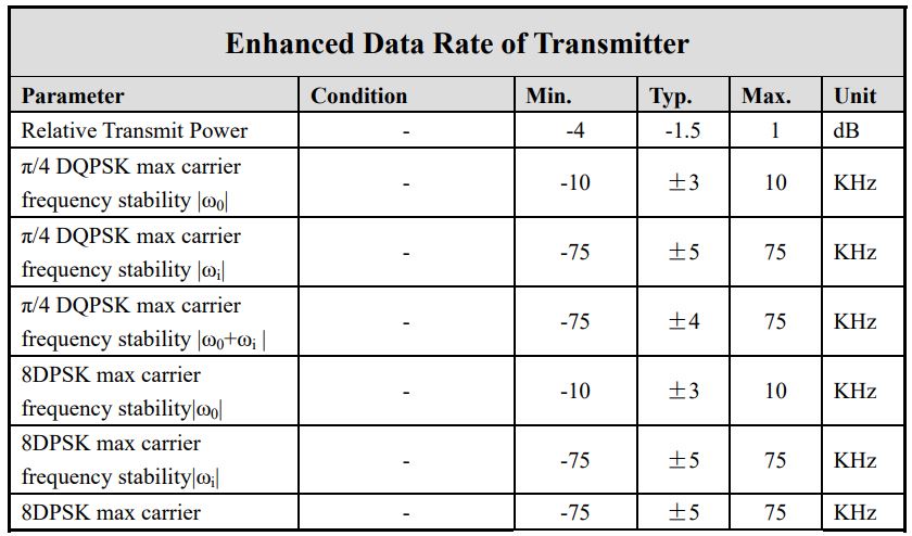
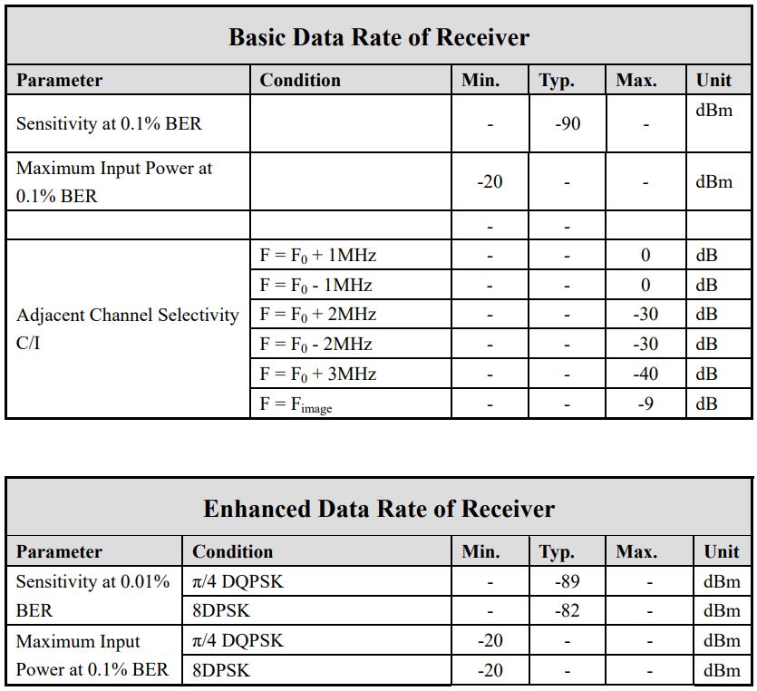
RF Characteristics

Module Pin definitions
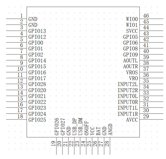
Pin Configurations


Module Package Information
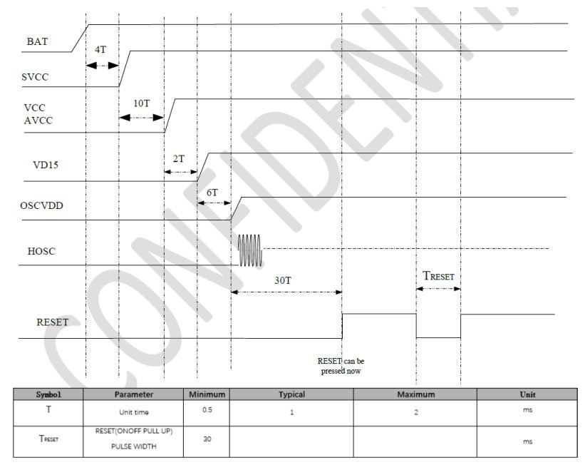
Power on sequence
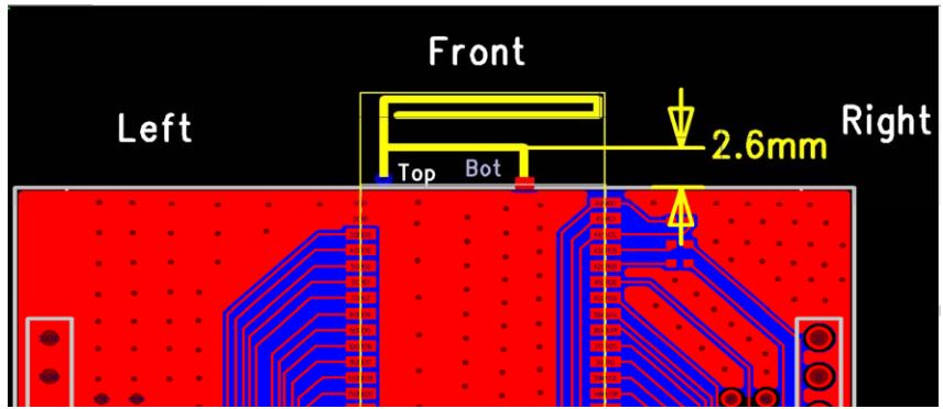
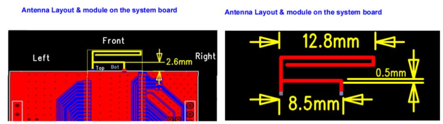
Recommended keep out area information
- It is recommended to place it at the end of the printed circuit board
- Clearance area size: the distance is greater than 2.5mm Do not place metal objects in front, left, right, up and down positions
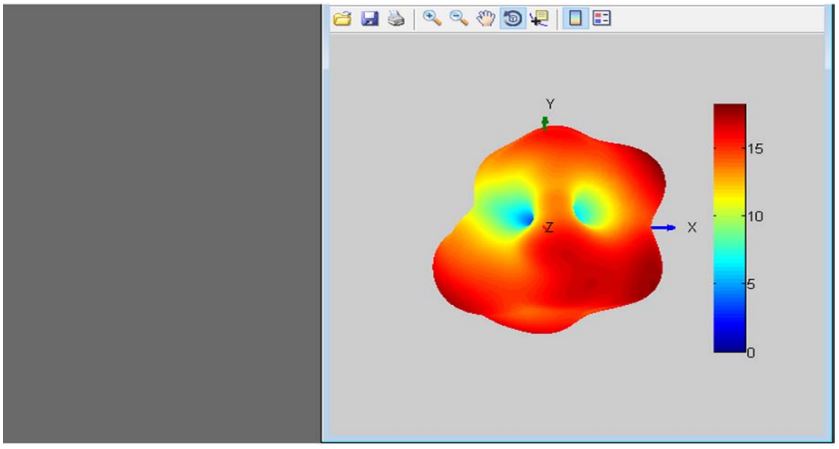
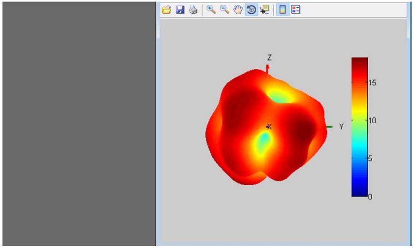
PCB antenna radiation pattern


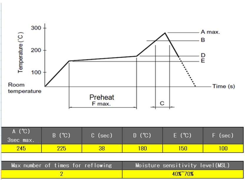
Soldering recommendations
Document History

FCC regulatory conformance FCC ID: SOP426421A This device complies with Part 15 of the FCC Rules. Operation is subject to the following two conditions: (1) This device may not cause harmful interference. (2) This device must accept any interference received, including interference that may cause undesired operation.
NOTE: This equipment has been tested and found to comply with the limits for a
Class B digital device, pursuant to part 15 of the FCC Rules. These limits are
designed to provide reasonable protection against harmful interference in a
residential installation. This equipment generates uses and can radiate radio
frequency energy and, if not installed and used in accordance with the
instructions, may cause harmful interference to radio communications. However,
there is no guarantee that interference will not occur in a particular
installation. If this equipment does cause harmful interference to radio or
television reception, which can be determined by turning the equipment off and
on, the user is encouraged to try to correct the interference by one or more
of the following measures:
– Reorient or relocate the receiving antenna.
– Increase the separation between the equipment and receiver.
-Connect the equipment into an outlet on a circuit different from that to which the receiver is connected.
-Consult the dealer or an experienced radio/TV technician for help
NOTE: Unauthorized changes will result in loss of device operating privileges.
RF Exposure This equipment complies with FCC RF radiation exposure limits set
forth for an uncontrolled environment.
IC regulatory conformance IC: 9569A-426421A This device complies with CAN ICES-003 (B)/NMB-003(B).This device contains licence-exempt transmitter(s)/receiver(s) that comply with Innovation, Science and Economic Development Canada’s licence-exempt RSS(s). Operation is subject to the following two conditions: (1) This device may not cause interference. (2) This device must accept any interference, including interference that may cause undesired operation of the device.
RF Exposure This equipment complies with IC RF radiation exposure limits set forth for an uncontrolled environment.
ORIGINAL EQUIPMENT MANUFACTURER (OEM) NOTES OEM must certify the final end
product to comply with unintentional radiators (FCC Sections 07 and 15.109)
before declaring compliance of the final product to Part 15 of the FCC rules
and regulations. Integration into devices that are directly or indirectly
connected to AC lines must add a new grant or SDOC. The OEM must comply with
the FCC labeling requirements. If the module’s label is not visible when
installed, then an additional permanent label must be applied on the outside
of the finished product which states: “Contains transmitter module FCC ID:
SOP426421A”. Additionally, the following statement should be included on the
label and in the final product’s user manual: “This device complies with Part
15 of the FCC Rules. Operation is subject to the following two conditions:
(1) This device may not cause harmful interferences, and (2) this device must
accept any interference received, including interference that may cause
undesired operation.” The module is limited to installation in mobile or fixed
applications. Separate approval is required for all other operating
configurations, including portable configuration with respect to Part 2.1093
and different antenna configurations. A module or modules can only be used
without additional authorizations if they have been tested and granted under
the same intended end-use operational conditions, including simultaneous
transmission operations. When they have not been tested and granted in this
manner, additional testing and/or FCC application filing may be required. The
most straightforward approach to address additional testing conditions is to
have the grantee responsible for the certification of at least one of the
modules submit a permissive change application. When having a module grantee
file a permissive change is not practical or feasible, the following guidance
provides some additional options for host manufacturers. Integrations using
modules where additional testing and/or FCC application filing(s) may be
required are: (A) a module used in devices requiring additional RF exposure
compliance information (e.g., MPE evaluation or SAR testing); (B) limited
and/or split modules not meeting all of the module requirements; and (C)
simultaneous transmissions for independent collocated transmitters not
previously granted together. This Module is full modular approval, it is
limited to OEM installation ONLY. Integration into devices that are directly
or indirectly connected to AC lines must a new grant or SDOC. (OEM) Integrator
has to assure compliance of the entire end product include the integrated
Module. Additional measurements (15B) and/or equipment authorizations (e.g.
Verification) may need to be addressed depending on co-location or
simultaneous transmission issues if applicable. (OEM) Integrator is reminded
to assure that these installation instructions will not be made available to
the end user.
IC labeling requirement for the final end product: The final end product must
be labeled in a visible area with the following “Contains IC: 9569A-426421A”
The Host Marketing Name (HMN) must be indicated at any location on the
exterior of the host product or product packaging or product literature, which
shall be available with the host product or online.
Unauthorized modifications could void the user’s authority to operate the
equipment.
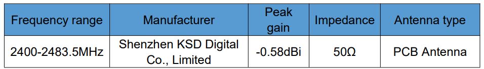
This radio transmitter [lC: 9569A-426421A] has been approved by Innovation,
Science and Economic Development Canada to operate with the antenna types
listed below, with the maximum permissible gain indicated. Antenna types not
included in this list that have a gain greater than the maximum gain indicated
for any type listed are strictly prohibited for use with this device.
Requirement per KDB996369 D03
2.2 List of applicable FCC rules
List the FCC rules that are applicable to the modular transmitter. These are
the rules that specifically establish the bands of operation, the power,
spurious emissions, and operating fundamental frequencies. DO NOT list
compliance to unintentional-radiator rules (Part 15 Subpart B) since that is
not a condition of a module grant that is extended to a host manufacturer. See
also Section 2.10 below concerning the need to notify host manufacturers that
further testing is required.3 Explanation: This module meets the requirements
of FCC part 15C(15.247).
2.3 Summarize the specific operational use conditions
Describe use conditions that are applicable to the modular transmitter,
including for example any limits on antennas, etc. For example, if point-to-
point antennas are used that require reduction in power or compensation for
cable loss, then this information must be in the instructions. If the use
condition limitations extend to professional users, then instructions must
state that this information also extends to the host manufacturer’s
instruction manual. In addition, certain information may also be needed, such
as peak gain per frequency band and minimum gain, specifically for master
devices in 5 GHz DFS bands. Explanation: The module has the fixed antennas do
not update the antenna trace and antenna type.
2.4 Limited module procedures
If a modular transmitter is approved as a “limited module,” then the module
manufacturer is responsible for approving the host environment that the
limited module is used with. The manufacturer of a limited module must
describe, both in the filing and in the installation instructions, the
alternative means that the limited module manufacturer uses to verify that the
host meets the necessary requirements to satisfy the module limiting
conditions. A limited module manufacturer has the flexibility to define its
alternative method to address the conditions that limit the initial approval,
such as: shielding, minimum signaling amplitude, buffered modulation/data
inputs, or power supply regulation. The alternative method could include that
the limited module manufacturer reviews detailed test data or host designs
prior to giving the host manufacturer approval. This limited module procedure
is also applicable for RF exposure evaluation when it is necessary to
demonstrate compliance in a specific host. The module manufacturer must state
how control of the product into which the modular transmitter will be
installed will be maintained such that full compliance of the product is
always ensured. For additional hosts other than the specific host originally
granted with a limited module, a Class II permissive change is required on the
module grant to register the additional host as a specific host also approved
with the module. Explanation: The module is not a limited module.
2.5 Trace antenna designs
For a modular transmitter with trace antenna designs, see the guidance in
Question 11 of KDB Publication 996369 D02 FAQ Modules for Micro-Strip
Antennas and traces. The integration information shall include for the TCB
review the integration instructions for the following aspects: layout of trace
design, parts list (BOM), antenna, connectors, and isolation requirements.
a) Information that includes permitted variances (e.g., trace boundary limits,
thickness, length, width, shape(s), dielectric constant, and impedance as
applicable for each type of antenna);
b) Each design shall be considered a different type (e.g., antenna length in
multiple(s) of frequency, the wavelength, and antenna shape (traces in phase)
can affect antenna gain and must be considered);
c) The parameters shall be provided in a manner permitting host manufacturers
to design the printed circuit (PC) board layout;
d) Appropriate parts by manufacturer and specifications;
e) Test procedures for design verification; and
f) Production test procedures for ensuring compliance. The module grantee
shall provide a notice that any deviation(s) from the defined parameters of
the antenna trace, as described by the instructions, require that the host
product manufacturer must notify the module grantee that they wish to change
the antenna trace design. In this case, a Class II permissive change
application is required to be filed by the grantee, or the host manufacturer
can take responsibility through the change in FCC ID (new application)
procedure followed by a Class II permissive change application. Explanation:
Yes, The module has the fixed antennas do not update the antenna trace and
antenna type.
2.6 RF exposure considerations
It is essential for module grantees to clearly and explicitly state the RF
exposure conditions that permit a host product manufacturer to use the module.
Two types of instructions are required for RF exposure information: (1) to the
host product manufacturer, to define the application conditions (mobile,
portable xx cm from a person’s body); and (2) additional text needed for the
host product manufacturer to provide to end users in their endproduct manuals.
If RF exposure statements and use conditions are not provided, then the host
product manufacturer is required to take responsibility of the module through
a change in FCC ID (new application). Explanation: This module complies with
FCC RF radiation exposure limits set forth for an uncontrolled environment.
This module is designed to comply with the FCC statement, FCC ID is:
SOP426421A.
2.7 Antennas A list of antennas included in the application for certification must be provided in the instructions. For modular transmitters approved as limited modules, all applicable professional installer instructions must be included as part of the information to the host product manufacturer. The antenna list shall also identify the antenna types (monopole, PIFA, dipole, etc. (note that for example an “omni-directional antenna” is not considered to be a specific “antenna type”)). For situations where the host product manufacturer is responsible for an external connector, for example with an RF pin and antenna trace design, the integration instructions shall inform the installer that unique antenna connector must be used on the Part 15 authorized transmitters used in the host product. The module manufacturers shall provide a list of acceptable unique connectors. Explanation: The module has the fixed antennas do not update the antenna trace and antenna type.
2.8 Label and compliance information Grantees are responsible for the continued compliance of their modules to the FCC rules. This includes advising host product manufacturers that they need to provide a physical or e-label stating “Contains FCC ID” with their finished product. See Guidelines for Labeling and User Information for RF Devices KDB Publication 784748. Explanation: The host system using this module, should have label in a visible area indicated the following texts: “Contains FCC ID: SOP426421A, Contains IC: 9569A-426421A ”
2.9 Information on test modes and additional testing requirements5
Additional guidance for testing host products is given in KDB Publication
996369 D04 Module Integration Guide. Test modes should take into consideration
different operational conditions for a stand-alone modular transmitter in a
host, as well as for multiple simultaneously transmitting modules or other
transmitters in a host product. The grantee should provide information on how
to configure test modes for host product evaluation for different operational
conditions for a stand-alone modular transmitter in a host, versus with
multiple, simultaneously transmitting modules or other transmitters in a host.
Grantees can increase the utility of their modular transmitters by providing
special means, modes, or instructions that simulates or characterizes a
connection by enabling a transmitter. This can greatly simplify a host
manufacturer’s determination that a module as installed in a host complies
with FCC requirements. Explanation: Top band can increase the utility of our
modular transmitters by providing instructions that simulates or characterizes
a connection by enabling a transmitter.
2.10 Additional testing, Part 15 Subpart B disclaimer
The grantee should include a statement that the modular transmitter is only
FCC authorized for the specific rule parts (i.e., FCC transmitter rules)
listed on the grant, and that the host product manufacturer is responsible for
compliance to any other FCC rules that apply to the host not covered by the
modular transmitter grant of certification. If the grantee markets their
product as being Part 15 Subpart B compliant (when it also contains
unintentional-radiator digital circuity), then the grantee shall provide a
notice stating that the final host product still requires Part 15 Subpart B
compliance testing with the modular transmitter installed. Explanation: The
module without unintentional-radiator digital circuity, so the module does not
require an evaluation by FCC Part 15 Subpart B. The host should be evaluated
by the FCC Subpart B.
Read User Manual Online (PDF format)
Read User Manual Online (PDF format) >>