BeSMART WiFi Thermostat Kit User Guide
- June 6, 2024
- BeSMART
Table of Contents
BeSMART WiFi Thermostat Kit User Guide

INSTALLATION
-
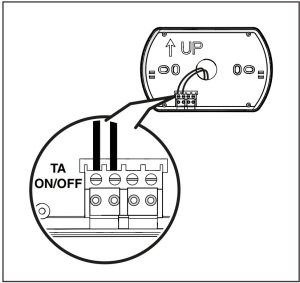
BeSMART: cablato in ON/OFF / Wired ON/OFF
-
WiFi Box: NON cablato (solo alimentato) / Wireless (only main supply)
-
BeSMART: NON cablato (wireless)/NOT cabled (Wireless)
-
WiFi Box: Cablato/ Wired
Note: for all other types of different installation refer to the installer manual.
GENERAL NOTICES
Safety
- A Avoid draughty areas
- B Do not install above heat sources
- C Avoid direct sunlight
- D Install at the correct height

Before installation
- Refer to the appliance manual to ensure that the BeSMART thermostat is compatible with your boiler.
- The BeSMART wireless thermostat can be installed almost everywhere within the home, however please refer to the adjacent diagrams for guidance when deciding on a suitable location.
- The BeSMART thermostat can also be used to replace an existing hard-wired thermostat (please check appliance manual to ensure compatibility).
- Switch off and isolate the appliance and any external controls from the electrical supply, before carrying out the installation.
Tools required for the installation
- Phillips screwdriver
- Small flat blade screwdriver
- Combination pliers
BeSMART installation
-
If necessary remove the old thermostat.

Warning: If its intended to re-use any existing wiring; you should refer to the appliance manual to ensure compatibility . -
Separate the BeSMART from the wall plate.

-
Fix the wall plate to the wall using the supplied screws (screw head inside proper location).

-
If using as a hard-wired control; connect the respective wiring to the relevant terminals on the BeSMART control.
Warning: Please refer to the appliance installation manual and the BeSMART manual for specific information on hard-wired connections. -
Insert two ‘AA’ type batteries (supplied), into the battery compartment.

Warning: Insert the batteries, observing the correct polarity as indicated. -
Re-attach the BeSMART thermostat to the wall plate by aligning and then pressing firmly around the outer edges.

WiFi Box installation
-
Attach the WiFi box to the appliance casing, using the magnetic pad located on the rear of the WiFi Box. Please check the ambient temperature is according the product specification as indicated on the installation manual. In case of low or null WiFi signal and with boiler RF receiver or WiFi Extender installed, place the WiFi Box in an ambient with a good WiFi signal (above 40%)

-
Using the mini USB cable and power adaptor (supplied); connect the WiFi box to an adjacent electrical socket .

-
Connect the (supplied) USB WiFi Box cable to the boiler OTBus connection (for specific boilers) or to the boiler room thermostat connection (TA or ON/OFF)
Warning: For the electrical connection and the technical specifications, please refer to the installation manual (OT PCB plug supplied as standard).
-
Attach the WiFi box to the appliance casing, using the magnetic pad located on the rear of the WiFi Box. Please check the ambient temperature is according the product specification as indicated on the installation manual. In case of low or null WiFi signal and with boiler RF receiver or WiFi Extender installed, place the WiFi Box in an ambient with a good WiFi signal (above 40%)

-
Insert the other end of the USB cable into the OUTPUTS/BOILER socket of the WiFi Box.
-
Using the mini USB cable and power adaptor (supplied); connect the WiFi box to an adjacent electrical socket .
INSTALLATION AND CONFIGURATION OF SMARTPHONE APP
-
Download and install the BeSMART APP on your Smartphone or tablet.
-
Create a user account following the steps indicated on the APP.
-
Link your user account to the ‘ID WiFi’ code that’s located on the side of the WiFi Box.
-
If required, it is possible to couple a boiler receiver or additional thermostats to the WiFi box using the following procedure: press and hold the WiFi LED button on the WiFi box until both red and green LEDs are flashing simultaneously. Place the item that is to be coupled, into the ‘coupling’ mode (see BeSMART instruction manual). When the coupling process has been completed, the system will automatically return to the normal operating condition.
-
A WiFi LED button

-
Use the password key of your ‘WiFi’ router to link the WiFi Box to your home network using one of the methods indicated below.
Waring: Smartphones or tablets must be connected to the WiFI network that will be matched to the WiFi Box.
ALARMS AND WORKING STATUS
| LED green | LED red | Status |
|---|---|---|
| F05 | Relè = bridged (sonly with ON/OFF installation) | |
| F1 | Relè = open (only with ON/OFF installation) | |
| ON | OTBus connection = OK (OT connection) | |
| ON | F01 | Boiler alarm (OTBus connection) |
| F05 F1 ON | ON | Network or RF error |
| F05 | F05 | WPS mode in progress (press and hold WPS button) – wait |
WPS signal
| F05| WPS signal detected
F05| F05| Smartlink mode in progress (press once Smartlink button)*
F1| F1| RF encoding in progress (press and hold the WiFi LED
button)
- Only for WiFi Box
LED
- ON = fixed ON
- F05 = flashing fast (0,5 secs)
- F1 = flashing slow (1 secs)
Alarm codes indicated on the BeSMART display and suggested corrective actions.
| Alarm | Description |
|---|---|
| Err | Temperature sensor broken. (not reparable – see BeSMART Instruction |
Manual)
E82| Radio frequency error (Check batteries/distance – see BeSMART
Instruction Manual)
E83| NO OTBus comunication (Check connections – see BeSMART Instruction
Manual)
E84| Hardware problems (not reparable, see BeSMART Instruction Manual)
A01…99| Boiler alarm (see boiler manual)
Customer Support
Web: www.hurlconheating.com.au
Email: info@hurlconheating.com.au
Tell: 1300 050 940
Read User Manual Online (PDF format)
Read User Manual Online (PDF format) >>