EGIS MOBILE ELECTRIC XD Series Single Flex 2 Relay-ACR Bi-Stable Relays Instruction Manual
- June 1, 2024
- EGIS MOBILE ELECTRIC
Table of Contents
- EGIS MOBILE ELECTRIC XD Series Single Flex 2 Relay-ACR Bi-Stable Relays
- Product Information
- Product Usage Instructions
- Install Guidelines & Dip Switch Settings
- General Specifications (Each Relay)
- Detailed Operational Modes & Responses
- INSTRUCTION
- XD Battery Disconnet – Competitor Compariosn / Cross Reference
- XD Relay Family Cluster Examples
- References
- Read User Manual Online (PDF format)
- Download This Manual (PDF format)
EGIS MOBILE ELECTRIC XD Series Single Flex 2 Relay-ACR Bi-Stable Relays

Product Information
Specifications:
- Input Voltage Range (Vdc): 8.0 – 36.0 Auto-Ranging
- Nominal Voltage (Vdc): 12, 24
- Over Voltage Protection (Vdc) (5 sec): 17.0, 34.0
- State Change Current (20 msec): 5.0 A, 3.0 A
- Standby Current (mA): 1.3
- Mechanical Switching Life: 1,000,000 cycles
- Operational Temperature Range: -40 to 105°C
- Ignition Protection: SAE J1171 / ISO 8846
Product Usage Instructions
Install Guidelines & Dip Switch Settings:
- DISCONNECT BATTERY FROM POWER DISTRIBUTION SYSTEM BEFORE INSTALLING PRODUCT TO PREVENT ELECTRICAL SHOCK OR PRODUCT DAMAGE
- INSTALL A 7.5 – 10.0 A FUSE ON THE BLACK GROUND RETURN WIRE
- DIP SWITCHES ARE SET FOR INDIVIDUAL RELAYS WITHIN DS1 determines the function of the device.
- If DS1 = OFF, relay will act as a simple Battery Disconnect Switch Remote Relay.
- If DS1 = ON, relay will operate as a Voltage Sensing Relay(VSR) and will utilize DS2-DS6 to determine VSR response per individual application requirements.
- DS2-DS3: Determines ON Trigger Voltage and delay settings.
- DS4-DS6: Determines OFF Trigger Voltage and device response to voltages below the setting.
General Specifications (Each Relay):
- Live Current Switching -50,000 cycles: 12V/300A, 24V/300A
- Hardware Material: Stainless Steel Self-Locking
- Terminal Stud Torque: 120 in-lbs
- LED/Aux Output Max Drive Current: 400 milli-Amps
- Typical Source Current for All Control Lines: 10 micro-Amps
FAQ:
Q: What is the warranty period for the XD Series Flex 2
Single/Double/Triple Bi-Stable Relays & VSR/ACRs?
A: The product comes with a 4 Year Industry Leading Warranty.
500 Amp Continuous Capability Per Relay /Extremely Compact Footprint
Available With or Without Intuitive Front
Facing Manual Override Knobs with Ability to
Lock Relays ON or OFF for Servicing
Sensing Relay, or Low Voltage Disconnect
Reproves Witering vl Raphs ement to Legacy
Remote ON/OFF/Auto Inputs Allows Forced
Close or Open or Allowing Automatic
Operation Based on Voltage Sensing
Local and Remote LED Indicators Per Relay Mechanical Only Contactor Options

Ultra-Low Power Draw: Lowest off-state current draw in industry (1.3 mA) combined.
Simple & Robust Installation: Sealed plugs/harnesses included.
Flexible Application Options: Install as a Remote Battery Disconnect Switch, Voltage Sensing Relay, or Low Voltage Disconnect. On/Off trigger via external signal and/or alternator voltage sense.
Diagnostic Feedback via optional external LEDs control lines and on-board LEDs for each relay
Bullet-proof Construction: Sealed unit, high temperature materials allow mounting anywhere on vehicle. Integrated thermal overload protection
Optional Kill Switch eliminates need for using thermal circuit breakers as service maintenance switches, reducing voltage drop to electrical loads.
Meets Stringent OEM Standards for electrical transient self-protection
4 Year Industry Leading Warranty
Install Guidelines & Dip Switch Settings
- DISCONNECT BATTERY FROM POWER DISTRIBUTION SYSTEM BEFORE INSTALLING PRODUCT TO PREVENT ELECTRICAL SHOCK OR PRODUCT DAMAGE
- INSTALL A 7.5 – 10.0 A FUSE ON THE BLACK GROUND RETURN WIRE
- DIP SWITCHES ARE SET FOR INDIVIDUAL RELAYS WITHIN AN XD RELAY WITH TWO OR MORE RELAY POSITIONS
DS1 determines the function of the device.
If DS1 = OFF, relay will act as a simple Battery Disconnect SwitCh Remote
Relay.
If DS1 = ON, relay will operate as a Voltage Sensing Relay (VSR) and will
utilize DS2-DS6 to determine VSR response per individual application
requirements
DS2-DS3: Determines 120 sec ON Trigger Voltage, 30 sec ON Voltage is 0.6 (1.2) Vdc higher. Once above this voltage, time delay to turning the relay ON is counting until ON event. If voltage is less than this setting, time delay is re-set to 0.
DS4-DS6: Determines OFF Trigger Voltage.
See methods of operation for device response to voltages below this setting.
Setting below 12.7 (25.4) Vdc allows accessory loads partial use of start
battery energy, while ensuring sufficient starting ability.
General Specifications (Each Relay)


Detailed Operational Modes & Responses
Relay Mode – Relay Closes (Turns ON) Immediately if:
-
Voltage on Either Input to Relay > 9 Vdc (minimum operating
Voltage) and either any of the following two conditions exist: -
Rem On/Off Ctri (Red) wire is connected to +Vdc (maintain if desire is for device to stay Closed) or
-
Momentary ON Signal Wire (Brown) is Connected to +Vdc Until Device Closes, Up to 3 seconds. (+Vdc may then remain or be removed while device remains Closed either way)
-
D51 = Off, Setting Device as an Simple Relay
Relay Mode – Relay Open (Turns OFF) Immediately it:
-
Voltage on Either Input to Relay > 9 Vdc (minimum operating
Voltage) and either any of the following three conditions exist: -
Rem On/Off CtrI (Red) wire changes from +Vdc to Floating or
-
Rem On/Off Ctrl (Red) wire is connected to Ground (may be momentarily or permanently connected for device to stay Closed) or
-
Momentary OFF Signal Wire (Green) is Connected to +Vdc Until
Device Opens, Up to 1 Second (+Vdc may then remain or be removed while device will remain Open either way) -
Rem Ctrl (Red) wire and Momentary ON Signal Wire (Brown) must not have +Vdc applied, they will override Off Signal from Green Wire
-
DS1 = Off, Setting Device as an Simple Relay
VSR Mode – Relay Closes (Turns ON) after 120 sec if:
- Voltage on Either Input > V_On as determined by DS2-DS3 and
- Rem Ctri (Red) wire is not connected to +Vdc or Gnd and
- Start Isolation Input Wires Sl#1 (Brown) and Sl#2 (Green) Not Connected to +Vdc
- DS1 = On, Setting Device as an Voltage Sensing Relay (VSR)
VSR Mode – Relav Closes (Turns ON) after 30 sec if:
- System as determined by to -DS andon + 0.6 V (2.2v it on 24v
- Rem Ctrl (Red) wire is not connected to +Vdc or Gnd
- Start Isolation Input Wires Sl#1 (Brown) and Sl#2 (Green) Not Connected to +Vdc
- DS1 = On, Setting Device as an Voltage Sensing Relay (VSR)
VSR Mode – Relay Automatically Opens (Turns OFF) if:
-
Voltage on Either Input < _Off as determined by DS4-DS6 and
-
Rem Ctrl (Red) wire is not connected to +Vdc or Gnd and
-
Start Isolation Input Wires Sl#1 (Brown) and Sl#2 (Green) are Not Connected to +Vdc and
-
D51 = On, Setting Device as an Voltage Sensing Relay and
-
At least 120 sec has passed since the device was either forced
Closed by the Red input wire or the device automatically Closed and -
The advanced charge management algorithm has determined that any electrical charging, if operating, is not equal to or great than the electrical loads discharging the connected batteries.
VSR Mode – Relay Opens (Turns OFF) after 15 sec if:
- Voltage on Either Input to Relay > Over-voltage set point for 15 continuous seconds and
- Rem Ctrl (Red) wire is not connected to +Vdc or Gnd
VSR Mode – Relay Immediately Closes (Turns ON) Immediately if:
- Voltage on Either Input > 9 Vdc (minimum operating Vdc) and
- Rem Ctri (Red) wire is connected to +Vdc
VSR Mode – Relay Immediately Opens (Turns OFF) immediately if:
-
Voltage on Either Input to Relay > 9 Vdc (minimum operating
Voltage) and either any of the following three conditions exist: -
Rem Ctrl (Red) wire is connected to Gnd
-
Start Isolation Input Wire SI#1 (Brown) is Connected to +Vac
-
Start Isolation Input Wire SI#2 (Green) is Connected to +Vdc
VSR Mode – Start Isolation Prevents Voltage Based Automatic Closing:
- For as long as one or more of the two Start Isolation Lines SI#1 and/or SI#2 have +Vdc applied on the wires
- For 3 minutes after +Vdc is no longer applied to both Start
Isolation Lines Sl#1 and/or SI#2 have +Vdc applied on the wires
Manual Override Prevents Remote or Voltage Based Open or Closing:
- For as long as the manual knob (if equipped) is not positioned in the “Auto/Rem” orientation
Upon Startup or Returning Device from Manual to Auto/Rem Mode:
- The remote LED will remain OFF regardless of the physical status of the VSR until the VSR is remotely forced ON/OFF or automatically attempts to turn itself ON/OFF.
- The local LED will rapid flash if the device has an input voltage that would dictate a pending ON or OFF is necessary.
INSTRUCTION
Fig 1 – Relay Mode – Control Wiring Options


Leaving Relay Input Ctrl Lines Floating / Not asserted to Bat +Vdc or Neg May Result in Unexpected Behavior in Wet Environments Subject to Bridging Corrosion
Fig 2 – Mechanical Only Contactor Option
XD Series Single, Dual, and Triple XD Relays are available with one or more positions constructed as a mechanical-only battery switch / mechanical contactor. This offers the option for certain application a more cost- effective solution to variations with all relay positions that are remote relays. See examples below

Fig 3 – XD Series Part Number Guide

Custom product configurations available including control harness wires, time delays,voltage settings, dip switch functionality, and control input functionality. Contact support@egismobile.com
Fig 4 – Triple XD Series – Dimensions


Fig 5 – Dual XD Series – Dimensions

Fig 6 – Single XD Series – Dimensions

Fig 7 – Triple XD – 88 Series (DTM Connectors) Diagram (Matches Legacy Remote Relay Solutions)
ALL relay positions capable of configuration as either Voltage Sensitive Relay (VSR) or Simple Remote Battery Disconnect via Dip Switches. Factory Dip Switch Settings are Per Part Number Per Table Referencing this Figure. For all relay positions set as VSRs,both input terminals adjacent to the relay position are used for sensing voltage and making automatic open/close decisions (VSR Mode Only)

Fig 8 – Triple XD – 87 Series (Connection Diagram)


Fig 9 – Triple XD – 87 Series (Mech Only Bat Sw)
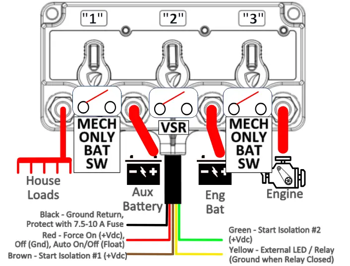
ALL switch positions capable of configuration as either VSR/ACR or Simple Relay via Dip Switches. Control wire responses change accordingly


Fig 11 – Triple XD – 88 Series (Single DT Conn)


Fig 12 – Dual XD – 87 Series (Flying Wires)


Mechanical Only (Mech Only) locations do not have an active remotely controllable relay or an automatic operation relay but instead offer only an “on-device” mechanical disconnect for that specific location


Fig 14 – Dual XD – 88 Series (Mounts Left of Triple)


Mechanical Only (Mech Only) locations do not have an active remotely controllable relay or an automatic operation relay but instead offer only an “on-device”mechanical disconnect for that specific location. No control wire terminations are present
XD Battery Disconnet – Competitor Compariosn / Cross Reference


- Excessive standby current drains batteries as no charge source is present potentially permanently damaging batteries and voiding battery warranties. The XD Series Standby current is 70% lower than the competitor’s auto-release version, and so low (1.2 mA) that on its own would take 9 years to drain a Group 31 battery.
- Copper terminal studs in general are susceptible to thread damage if excessive assembly torque on the attachment nut is applied. The result is stripping of the threads and spinning of the nut; and a reduction or loss of clamping force between the cable terminal and device terminal. This can result in increased resistance and possibly overheating of the device and power cables.
- Studs parallel to the mounting surface require right-angle cable terminal lugs to achieve bottom cable entry
- IP67 and IP6K9K are standard marine / harsh environment ingress performance levels to ensure effective long-term performance. Customers are encouraged to independantly evaluate legacy product to water entry susceptibility.
- XD Series products are also available in single housing double and triple relay versions which provide significant cost, space, and standby current draw benefits versus existing industry options.
- XD Series mounting footprint is 60% smaller and much lighter, critical in today’s systems with very limited space allocated for power management and where the affect of total system weight on vessel/vehicle performance has received greater attention.


XD Series Dual and Triple Relays can be configured to have each individual internal relay replicate legacy competitor product functionality and connect with external controls with the same DTM connector and pin-out locations, simplifying product transition.
XD Relay Family Cluster Examples
Triple Battery Relay / VSR Cluster

Quad Battery Bank Relay / VSR Cluster

www.egismobile.com 360.768.1211 Bellingham, WA U.S.A
References
Read User Manual Online (PDF format)
Read User Manual Online (PDF format) >>