Fanless Tech DS50U Series Mini PC User Guide
- June 16, 2024
- Fanless Tech
Table of Contents
Fanless Tech DS50U Series Mini PC User Guide

More information on this product can be found at: https://bit.ly/DS50USERIES
Product Overview

- USB 3.2 Gen 2 Ports
- USB 3.2 Gen 1 Ports
- Power LED
- Hard Disk Drive LED
- Power Button
- MIC-in
- Headphones
- HDMI Port
- DisplayPort
- COM Port (RS232/RS422/RS485) (BIOS Setting)
- USB 2.0 Ports
- Giga LAN Port
- 2.5Giga LAN Port
- Power Jack (DC IN)
- COM/VGA Port (RS232 only) (Option)
- Connector for WLAN antenna
- External Power SW & Clear CMOS
- Kensington® Lock Hole
Hardware Installation
A. Begin Installation
For safety reasons, please ensure that the power cord is disconnected before opening the ca
- As shown, unscrew the four screws of the chassis cover and remove the cover.
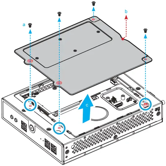
The product’s colour and specifications may vary from the actually shipped product.
B. HDD or SSD Installation
-
As shown, remove the rack.
-
Mount the HDD or SSD into the bracket with four screws.
-
Connect the Serial ATA and power cable to the HDD or SSD.
-
Install the HDD or SSD & bracket in the chassis.

C. Memory Module Installation
This motherboard does only support 1.1 V DDR5 SO-DIMM memory modules.
-
Locate the SO-DIMM and paste the thermal pad (50*15 mm) on the motherboard, which can effectively reduce its temperature.
-
Install the 1st memory module into the DIMMA1 slot. 45-degree angle

-
Gently insert the module into the slot in a 45-degree angle.

-
Align the notch of the memory module with the one of the relevant memory slot.

-
Carefully push down the memory module until it snaps into the locking mechanism and put the mylar back in place.
-
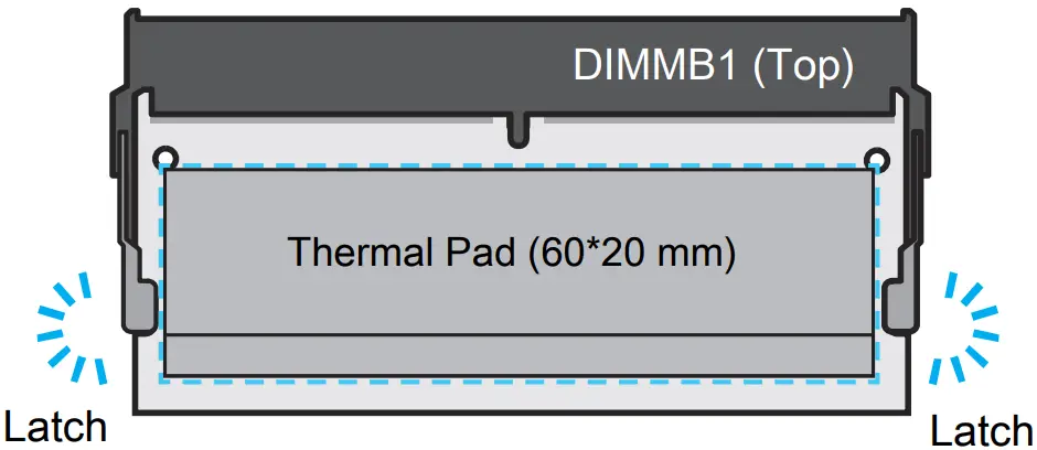
Install the 2nd memory module into the DIMMB1 slot (proceed with steps B3 to B5) and paste the thermal pad, as shown.
D. M.2 Device Installation
Notice for M.2 slots: When CN3 is occupied by NVME device, CN2 only support
SATA interface.

DS50U only support one NVME device.
-
Locate the M.2 key slots on the motherboard.
- M.2 2280 M key slot

- M.2 2280 M key slot
-
Install the M.2 device into the M.2 slot and secure with the screw.

Pasting a thermal pad on the M.2 SSD can effectively reduce its temperature.
E. Complete
- Please replace and affix the case cover with four screws. Turn your DS50U upside down.
- Connect the power cord.
- Complete.

Please press the “Del” key while booting to enter BIOS. Here, please load the
optimised BIOS settings.
Operation Position: Please make sure to use either the supplied feet or the
VESA mount.
Safety Information
Incorrectly replacing the battery may damage this computer. Replace only with the same or equivalent as recommended by Shuttle. Dispose of used batteries in accordance with the laws of your country.
WARNING
THIS PRODUCT CONTAINS A BUTTON BATTERY
This device complies with Part 15 of the FCC Rules. Operation is subject to the following two conditions: (1) this device may not cause harmful interference, and (2) this device must accept any interference received, including interference that may cause undesired operation.
This device meets the requirements for the EU conformity in accordance to the currently valid EU directives.
Motherboard Illustration

- USB 3.2 Gen 2 Ports
- USB 3.2 Gen 1 Ports
- Power LED
- Hard Disk Drive LED
- Power Button
- MIC-in
- Headphones
- DDR5 SO-DIMM Slots
- Processor
- SATA 3.0 6Gb/s connector
- M.2 2280 M key slot
- M.2 2280 M key slot
- M.2 2230 E Key Slot
- Battery Connector
- USB 2.0 Ports
- DisplayPort
- HDMI Port
- COM Port
- Giga LAN Port
- 2.5Giga LAN Port
- Power jack (DC IN) \ DC
J1
Connector for SD Card Reader Daughter Board (CR005)
SD1
Pin| Signal Name
1| +3.3VS
2| +3.3VS
3| GND
4| USB_D-
5| USB_D+
6| GND
J2
AC Back Auto Power ON
Open (enabled)
**Short (disabled)
**
JP1
Pin| Signal Name
1| AUTO_PWR_ON
2| GND
J3
COM 2 Port

COM2 (RS232)
Pin| Signal Name
1| DCD
2| RXD
3| TXD
4| DTR
5| GND
6| DSR
7| RTS
8| CTS
9| RI
10| NULL
J4
COM 1 & COM 2 Power Switch
JP2
COM1 (pin9)| COM2 (pin9)
Short Pin| Function| Short Pin| Function
1-2 (Default)| RI1| 3-4 (Default)| RI2
5-7| +5V| 6-8| +5V
7-9| +12V| 8-10| +12V
J5
VGA connector
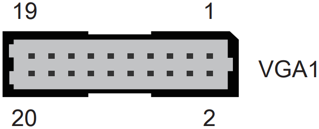
VGA1
Pin| Signal Name| Pin| Signal Name| Pin| Signal Name| Pin| Signal Name
1| GND| 2| GND| 3| SCL| 4| GND
5| SDA| 6| GND| 7| GND| 8| GND
9| VSYNC| 10| GND| 11| HSYNC| 12| GND
13| GND| 14| GND| 15| BOUT| 16| +5V
17| GOUT| 18| +5V| 19| ROUT| 20| +5V
J6
External Power SW & Clear CMOS
SW2
Pin| Signal Name| Pin| Signal Name
1| PWR_SW_N| 2| +5V
3| GND| 4| RTC_RST_N
References
Read User Manual Online (PDF format)
Read User Manual Online (PDF format) >>