PREMIER MOUNT 7170-0978 Series Outdoor Flat Tilt Wall Mount Installation Guide
- June 13, 2024
- PREMIER MOUNT
Table of Contents
PREMIER MOUNT 7170-0978 Series Outdoor Flat Tilt Wall Mount

BASIC INFORMATION
Wall mount model 7170-0978-00 (Flat) 7170-0978-01 (Tilt)
Display Model OH75
Installation Configuration Landscape
Tilt feature Available by model Fixed at flat, 5 deg, 10 deg , 15 deg
Environment Temperature Negative 30 Celsius to 50 Celsius, 24/7 operation
Wall application Solid concrete, Hollow Brick, or 3/4″ plywood-backed
wall
Product Weight 53.3 lbs [20.6kg] for flat model 72.3 lbs [32.8kg] for
tilt model
OA Weight (Mount & Flat-Panel) 366.4 lbs [166.2 kg] (flat) 385.4 lbs
[174.8 kg] (Tilt)
OA Width x Depth x Height (Landscape) 69.87” x (12.59” flat to 23.066”
tilt) x 41.47”
INSTALLATION ENVIRONMENT
Beach Must not be placed in areas where seawater is accessible
Wind Must not be placed in areas with strong winds caused by storms or
other natural phenomenon
Snow Awning or cover is needed to avoid snow piling directly onto inlet
Iron Dust Suitable, (e.g. train or subway station)
ENCLOSED OR RECESS AREA
Clearance 200mm (7.88”) minimum all around
Additional front glass Prohibited in any enclosed area
CORE COMPONENTS

HARDWARE
-
1/4-20 x 5” Pan
Head

-
1/4-20” x 3/4”
Button Head

-
1/4” Flat Washer

-
5/16” x 3” Hex
Lag

-
5/16” Split Lock
Washer

-
5/16” Flat
Washer

-
Shell Expansion
Anchor

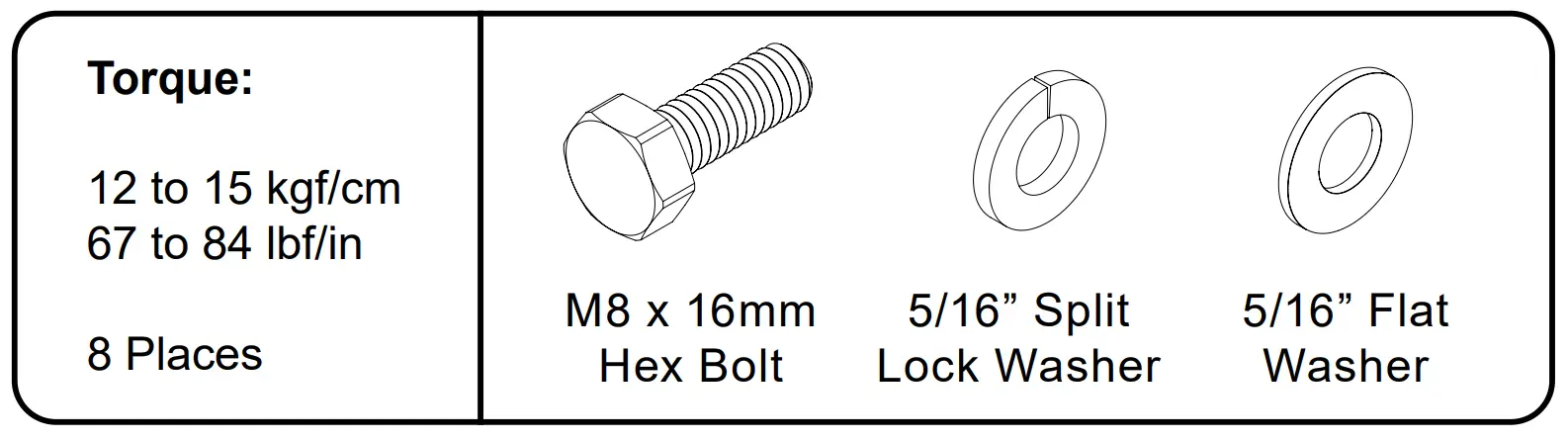
-
M8 x 16mm Hex
Bolt

-
Lock-it
Security Barrel

TILT ADAPTER (OPTION)

-
1/4-20” x 2-1/2”
Button Head

-
1/4” Flat Washer

Installation Instructions


Install flat or tilt brackets in landscape.

Use 1/4-20” x 3/4” button head screw with washer to secure the support bracket into the frame.


Solid Concrete/Brick
Use proper mounting guideline per state code

Brick (Alternative)
All hardware, threaded rod, epoxy, and other mounting hardware are not supplied. Shown for reference only.

Wood Application
Use a stud finder to determine the center of the wall studs in the vicinity of the mount and mark the wall. Drywood wall must be backed with at least 3/4” plywall to support the weight of the mount and flat-panel.

Requires a minimum of 6 mounting screws on upper slots and 2 on bottom slots. Shell expansion anchors are suitable for both concrete and brick.

Requires at least 6 mounting screws into wood stud and 4 mounting screws on the upper slots. Shell expansion anchors are not used for this application.

MOUNTING DIMENSIONS
| Letter | Description | Portrait |
|---|---|---|
| A | Net Height | 44.66” [1134.4mm] |
| B | Tilt offset (Top) | 4.59” [116.6mm] |
| C | Tilt offset (Bottom) | 3.19” [81.1mm] |
| D | Bottom to mounting slot of the wall plate | 20.27” [514.86mm] |
| E | Minimum clearance of recess area | 60.43” [1532.9mm] |

| Angle | Depth |
|---|---|
| Flat | 12.59” [319.8mm] |
| 5 | 16.18” [411.0mm] |
| 10 | 19.71” [500.6mm] |
| 15 | 23.07” [586.0mm] |


SECURITY FEATURE
Lock the security barrel to prevent the mount from being tampered or disengaged.


Read User Manual Online (PDF format)
Read User Manual Online (PDF format) >>