OOBIK BS-50 Cycling Speed and Cadence Dual Sensor Instruction Manual
- June 5, 2024
- OOBIK
Table of Contents
OOBIK BS-50 Cycling Speed and Cadence Dual Sensor

IMPORTANT INSTRUCTION
Warning
- This product contains a coin / button cell battery.
- If the coin / button cell battery is swallowed, it can cause severe internal burns in just 2 hours and can lead to death.
- Keep new and used batteries away from children.
- If the battery compartment does not close securely, stop using the product and keep it away from children.
- If you think batteries might have been swallowed or placed inside any part of the body, seek immediate medical attention.
Specification
- Product : Cycling Speed & Cadence Dual Sensor
- Model : B SHARK (BS-50)
- Size : 48 x 43 x 27 mm
- Weight : 25g ( Incl. Battery & Magnet )
- Battery type : CR2032 (DC 3V)
- Battery Life : Up to 600h
- Temperature : -20℃ to 60℃
- Range : 120km/h, 260rpm
- Wireless : Bluetooth 5.0, ANT+
Warranty & Service
- This product was shipped after its own quality/management inspection and is sold in accordance with consumer compensation regulations.
- The warranty period is one year from the date of purchase of the product
- In the event of a failure in normal use within the warranty period, contact the service center and send the receipt and product to us for free of charge.
- Paid service items
- Products that warranty has expired..
- Failure/damage cause by user negligence or accident
Component

Battery install / Replace
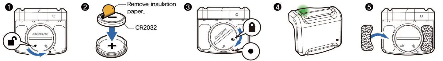
- Remove Battery cover : and rotate consistently to separate the cover.
- Inserting battery : Remove the insulating paper attached to the (-) terminal of the CR2032 battery and insert it into the battery cover.
- Insert Battery Cover : Insert the center point of and to match press to close completely, and install the cover to match and .
- Confirm operation : Battery contact and green LED flashing. (※ Refer to‘ 8. LED Display Status’)
- Dual lock pad attachment : Remove protective film on the back of the dual lock pad and attach it to the left and right grooves of the sensor’s battery cover
Install position & Check magnet detection.
Check: Before attaching the dual lock pad, refer to ‘6. Installation check
whether detects a magnet for each sensor.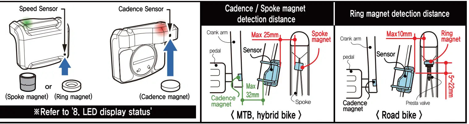
Installation
A. Sensor and cadence magnet
- Cadence Magnet Attachment Attaches to the pedal bolt groove of the crank arm.
- Attach dual lock pad frame.
- Remove the protective film on the back of the dual lock pad and attach it to the inner side of the rear wheel frame where the sensor is installed.
Install sensor & 2nd fix with rubber ring
- Attach the sensor in the direction of the arrow to the dual lock pad for the frame.
- The sensor attached to the dual lock pad for frame can be detached/attached.)
- Fix the body to the frame one more time using the rubber ring and the body fixing groove. (see below picture
 B. Speed sensor magnet
Spoke magnets
- Unscrew the screw cap attached to the spoke magnet, attach it to the spoke so that the magnet faces the speed sensor, and then turn the screw cap again to fix it.
- If the sensor and spoke magnet collide, attach it to the opposite side.)
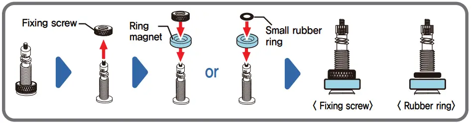
Ring magnet
- For Presta valve only, may not be possible depending on rim and valve specifications.)
- Separate the fixing screw at the bottom of the air inlet as shown below.
- Insert the ring magnet first, then insert the fixing screw or small rubber ring to fix it.
Cautions for park/stop
LED display status (Power saving mode about 30 min after stop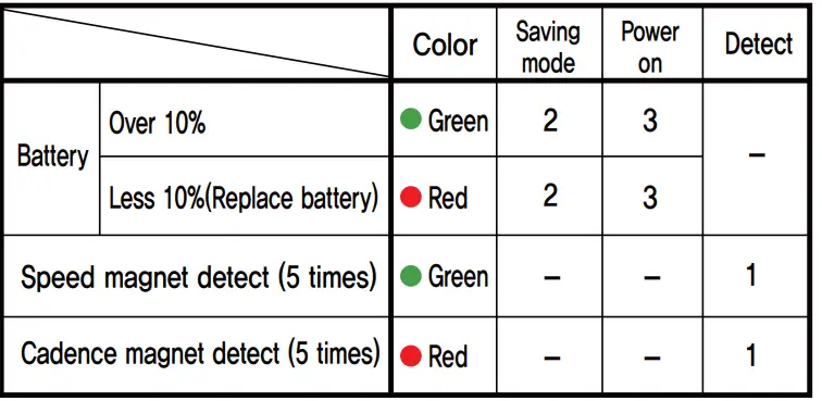
FCC RULES
This device complies with part 15 of the FCC Rules. Operation is subject to the following two conditions:
- This device may not cause harmful interference, and
- this device must accept any interference received, including interference that may cause undesired operation.
Any changes or modifications (including the antennas) to this device that are not expressly approved by the manufacturer may void the user’s authority to operate the equipment. This equipment complies with FCC RF Radiation exposure limits set forth for an uncontrolled environment. This device and its antenna must not be co-located or operating in conjunction with any other antenna or transmitter.
References
Read User Manual Online (PDF format)
Read User Manual Online (PDF format) >>