MiaoMing WD8822CS WiFi Module User Manual
- June 15, 2024
- MiaoMing
Table of Contents
- Introduction
- Overview
- Product Features
- Applications
- GENERAL SPECIFICATION
- WIFI RF Specifications
- BT RF Specifications
- Operating Conditions
- Mechanical Specification
- Environmental Requirements
- Patch WIFI modules installed before the notice:
- PACKING INFORMATION
- Operation Frequency:
- Trace antenna designs
- Antennas
- OEM integration instructions:
- FCC STATEMENT :
- Read User Manual Online (PDF format)
- Download This Manual (PDF format)
MiaoMing WD8822CS WiFi Module User Manual
Introduction
Overview
The Realtek RTL8822CS-VS-CG is a highly integrated single-chip that support 2-stream 802.11ac solutions with Multi-user MIMO (Multiple-Input, Multiple- Output) with integrated Bluetooth Smart Ready controller, SDIO (SDIO 1.1/2.0/3.0) interface, and HS-UART mixed interface. It combines a WLAN MAC, a 2T2R capable WLAN baseband, and RF in s single chip. The RTL8822CS-VLCG provides a complete solution for a high-performance integrated wireless and Bluetooth device.
The RTL8822CS-VS-CG baseband implements Multi-user Multiple Input, Multiple Output (MU MIMO) Orthogonal Frequency Division Multiplexing (OFDM) with two transmit and two receive paths (2T2R). Features include two spatial stream transmissions, short Guard Interval (Gl) of 400ns, spatial spreading, and support for variant channel bandwidth. Moreover, RTL8822CS-VS-CG provides one spatial stream space-time block code (STBC), Transmit Beamforming (TxBF) and Low Density Parity Check (LDPC) to extend the range of transmission. At the receiver, extended range and good minimum sensitivity is achieved by having receiver diversity up to 2 antennas. As the recipient, the RTL8822CS-VS-CG also supports explicit sounding packet feedback that helps senders with beamforming capability.
For legacy compatibility, Direct Sequence Spread Spectrum (DSSS), Complementary Code Keying (CCK) and OFDM baseband processing are included to support all IEEE 802.11b, 802.11g and 802.11a data rates. Differential phase shift keying modulation schemes, DBPSK and DQPSK with data scrambling capability are available, and CCK provides support for legacy data rates, with long or short preamble. The high speed FFT/IFFT paths, combined with BPSK, QPSK, 16QAM, 64QAM and 256 QAM modulation of the individual subcarriers, and rate compatible coding rate of 1/2, 2/3, 3/4, and 5/6, provide up to 866.7Mbps for IEEE 802.11ac MIMO OFDM.
TheRTL8822CS-VS-CG builds in an enhanced signal detector, an adaptive frequency domain equalizer, and a soft-decision Viterbi decoder to alleviate severe multi-path effects and mutual interference in the reception of multiple streams. For better detection quality, receive diversity with Maximal-Ratio- Combine (MRC) applying up to two receive paths is implemented. Robust interference detection and suppression are provided to protect against Bluetooth, cordless phone, and microwave oven interference.
Receive vector diversity for multi-stream application is implemented for efficient utilization of the MIMO channel. Efficient IQ-imbalance, DC offset, phase noise, frequency offset, and timing offset compensations are provided for the radio frequency front-end
The RTL8822CS-VS-CG supports fast receiver Automatic Gain Control(AGC) with synchronous and asynchronous control loops among antennas, antenna diversity functions, and adaptive transmit power control functions to obtain better performance in the analog portions of the transceiver
The RTL8822CS-VS-CG MAC supports 802.11e for multimedia applications, 802.11i
and WAPI (Wireless Authentication Privacy Infrastructure) for security, and
802.11n/802.11ac for enhanced MAC protocol efficiency. Using packet
aggregation techniques such as A-MPDU with BA and A-MSDU, protocol efficiency
is significantly improved. Power saving mechanisms such as Legacy Power Save,
U-APSD, and MIMO power saving reduce the power wasted during idle time, and
compensate for the extra power required to transmit MIMO OFDM. The RTL8822CS
provides simple legacy, 20MHz/40MHz/80MHz co-existence mechanisms to ensure
backward and network compatibility.
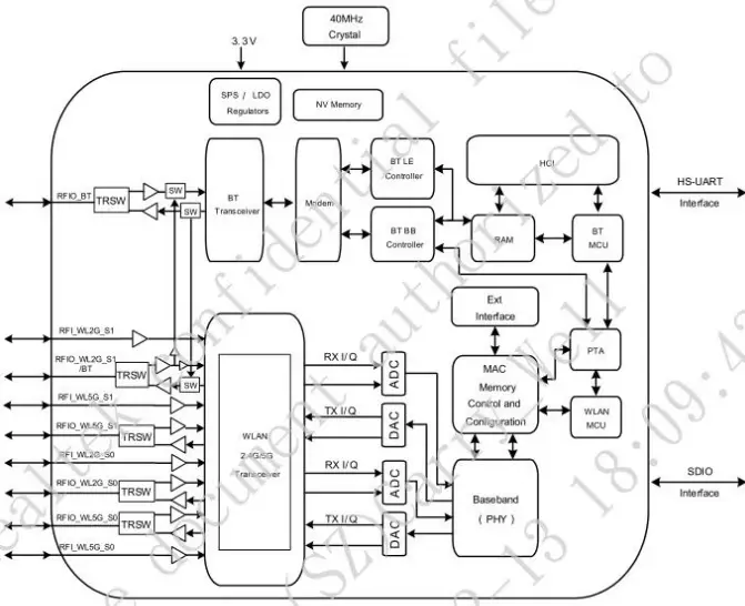
Figure 1. Duai-Band MIMO 2×2 Solution (i11ac 2×2 MAC/BB/RF + PA) and
Integrated Bluetooth Controller Solution — RTL8822CS-VL-CG.
Product Features
- IEEE 802.11 a/b/g/n and 802.11ac draft compliant
- Supports low power SDIO3.0 interface for WLAN and HS-UART interface for Bluetooth.
- Supports Bluetooth 4.0 Dual Mode and compatible with Bluetooth V2.1 and v3.0 and 5.0 systems,
- Supports WLAN-Bluetooth coexistence
- Support 20MHz, 40MHz, 80MHz in 5GHz band, and 20MHz, 40MHz bandwidth in 2.4GHz band
- Dual-band 2T2R mode with data rate up to 867Mbps
- Support 256QAM in 2.4GHz band
- Support standard SDIO v3.0 (up to SDR104 mode at 208MHz ) host interfaces
- Security support for WFA WPA/WPA2 personal, WPS2.0, WAPI
Applications
- NOTE-BOOK
- TV
- Tablet PC
- Set-Top box
GENERAL SPECIFICATION
WIFI RF Specifications
| Features | Descriptions |
|---|---|
| Main Chipset | RTL8822CS-VS-CG |
| Frequency Range | 2.4G WIFI:2412-2472 MHz5G:5180-5240 MHz,5260-5320 |
MHz,5500-5700MHz,5745-5825 MHz
Host Interface| WiFi:SDIO 2.0/3.0
Standards| WiFi: IEEE 802.11a, IEEE 802.11b, IEEE 802.11g, IEEE
802.11n, IEEE 802.11ac,
Modulation| WiFi: 802.11b: DSS/CCK 802.11 a/g/n/ac: OFDM
PHY Data rates| WiFi: 802.11a: 54,48,36,24,18,12,9,6 Mbps 802.11b:
11,5.5,2,1 Mbps 802.11g: 54,48,36,24,18,12,9,6 Mbps802.11n: up to 300Mbps
802.11ac: up to 867Mbps
Transmit Output Power| *** 2.4WiFi: 19.19dBm
| 5G WIFI: 19.88dBm; BT:8.34 dBm BLE:5.76 dBm
EVM| 802.11b /11Mbps : EVM ≤ -9dB 802.11a /g 54Mbps : EVM ≤ -25dB 802.11n
/MCS7 : EVM ≤ -28dB(2.4G/5.8G) 802.11n /MCS9 : EVM ≤ -32dB(5.8G)
Receiver Sensitivity 2.4G| 802.11b@8% PER Receive maximum level ≥-10 11Mbps ≤
-82dBm
| 802.11g@10% PER Receive maximum level ≥-20 54Mbps ≤ -72dBm
| 802.11n@10% PER Receive maximum level ≥-20 MCS 7_HT20 ≤ -70 dBmMCS
7_HT40 ≤ -66 dBm
Receiver Sensitivity 5.8G| 802.11a@10% PER Receive maximum level ≥-30
54Mbps ≤ -70dBm
| 802.11n/ac@10% PER Receive maximum level ≥-30MCS 7_HT20 ≤ -67 dBmMCS
7_HT40 ≤ -65 dBm MCS 9 ≤ -63dBm (HT 80)
Operating Channel| WiFi 2.4GHz: 11: (Ch. 1-11) – United States(North America)
13: (Ch. 1-13) – Europe14: (Ch. 1-14) – Japan
Operating Channel| WiFi 5.8GHz:
| 
Media Access Control| WiFi: CSMA/CA with ACK
Network Architecture| WiFi: Ad-hoc mode (Peer-to-Peer ) Infrastructure mode
Software Amplify Direct
Security| WiFi: WEP, TKIP, AES, WPA, WPA2
Antenna| External
OS Supported| Android / Linux
Dimension| Typical L15.0 mm W13.0 mm *H2.5mm (+/-0.2mm)
BT RF Specifications
| Feature | Description |
|---|---|
| Bluetooth Standard | Bluetooth V5.0 of 1, 2 and 3 Mbps. |
| Frequency Band | 2.402~2.48GHz |
| Channel numbers | 79 (0~78) |
| Min | Typical |
| Output Power (Class 1.5) | |
| Output Power (Class 2) | |
| Sensitivity @ BER=0.1% for GFSK (1Mbps) | |
| Sensitivity @ BER=0.01% for π/4-DQPSK (2Mbps) | |
| Sensitivity @ BER=0.01% for 8DPSK (3Mbps) |
Operating Conditions
| Parameter | Min. | Typ. | Max. | Unit |
|---|---|---|---|---|
| Operating Temperature | 0 | – | +70 | ℃ |
| Operating Humidity | 10 | – | 85 | % |
| VCC33 | 3.15 | 3.3 | 3.45 | V |
| VDDIO | 1.7 | 1.8 or 3.3 | 3.45 | V |
| External power supply current design | ≥ 1200mA |
Mechanical Specification
Outline Drawing (Uni it: +£0.2mm)

PCB Layout

PIN Assignment

| Pin # | Name | Description |
|---|---|---|
| 1.3.4.5.6.7.8.10.11.23.32.39.46.48 | GND | Ground connections |
| 2 | RF_S1 | RF I/O port chain1 |
| 9 | RF_S0 | RF I/O port chain0 |
| 26.33.35.37.47 | NC | No connect |
| 12 | BT_ANT0 | BT_ANT0 |
| 13 | GPIO6 | NC |
| 14 | G_BT | NC |
| 15 | WL_DIS_N | Enable pin for WLAN device ON: pull high ; OFF: pull low |
| 16 | SD_WAKE | WLAN to wake-up HOST |
| 17 | SDIO_CMD | SDIO command line |
| 18 | SDIO_ CLK | SDIO clock line |
| 19 | SDIO_D3 | SDIO data line 3 |
| 20 | SDIO_D2 | SDIO data line 2 |
| 21 | SDIO_D0 | SDIO data line 0 |
| 22 | SDIO_D1 | SDIO data line 1 |
| 24 | SD_WAKE | WLAN to wake-up HOST |
| 25 | GPIO7 | NC |
| 27 | PCM_SYNC | PCM sync signal |
| 28 | PCM_IN | PCM data input |
| 29 | PCM_OUT | PCM Data output |
| 30 | PCM_CLK | PCM clock |
| 31 | SUSCLK | External Low Power Clock input |
| 34 | VDD_IO | I/O Voltage supply input 1.8V or 3.3V |
| 36 | VCC33 | Main power voltage source input 3.3V |
| 38 | BT_DIS_N | Enable pin for Bluetooth device ON: pull high ; OFF: pull |
| 40 | UART_TX | Bluetooth UART interface |
| 41 | UART_RX | Bluetooth UART interface |
| 42 | UART_RTS | Bluetooth UART interface |
| 43 | UART_CTS | Bluetooth UART interface |
| 44 | SD_RESET | RESET |
| 45 | G_WL | NC |
| 49 | BT_WAKE | HOST wake-up Bluetooth device |
| 50 | UART_WAKE | External Low Power Clock input |
WIFI RF Circuit reference pictures

NOTE : Antenna design requirements
- RF-line need 50 Q single line impedance;
- Layout is arc line or straight line;
- Parameter need adjustment according to different antenna;
- Please antenna close to the WIFI module, its farthest distance can not exceed 20 mm.
Environmental Requirements
Operating & Storage Conditions
| Operating | Temperature: 0°C to +70°C |
|---|---|
| Relative Humidity: 10-85% (non-condensing) | |
| Storage | Temperature: -40°C to +80°C (non-operating) |
Relative Humidity: 5-90% (non-condensing)
Recommended Reflow Profile
Referred to IPC/JEDEC standard.
Peak Temperature : <250°C
Number of Times : <2times
Patch WIFI modules installed before the notice:
WIFI module installed note:
- Please press 1 : 1 and then expand outward proportion to 0.7 mm, 0.12 mm thickness When open a stencil
- Take and use the WIFI module, please insure the electrostatic protective measures.
- Reflow soldering temperature should be according to the customer the main size of the products, such as the temperature set at 250 + 5 ‘C for the MID motherboard.
About the module packaging, storage and use of matters needing attention are as follows:
-
The module of the reel and storage life of vacuum packing: 1). Shelf life: 8 months, storage environment conditions: temperature in: < 40 °C, relative humidity: < 90% r.h.
-
The module vacuum packing once opened, time limit of the assembly:
Card: 1) check the humidity display value should be less than 30% (in blue), such as: 30% ~ 40% (pink), or greater than 40% (red) the module have been moisture absorption. -
factory environmental temperature humidity control: = 30 ‘C, = 60% r.h..
-
Once opened, the workshop the preservation of life for 168 hours.
-
Once opened, such as when not used up within 168 hours:
-
The module must be again to remove the module moisture absorption.
-
The baking temperature: 125 °C, 8 hours.
-
After baking, put the right amount of desiccant to seal packages
PACKING INFORMATION
Blister packaging
**Top
Bottom

**
Note: Shenzhen MiaoMing may make improvements and/or changes in this
document or in the product described in this document at any time. This
document could include technical inaccuracies or typographical errors.
Shenzhen MiaoMing Intelligent Technology Co., Ltd Reserves the final
interpretation power Integration instructions for host product manufacturers
according to KDB 996369 D03 OEM Manual vO1
List of applicable FCC rules
FCC Part 15 Subpart C 15.247 & 15.207 & 15.209 & 15.407
Specific operational use conditions
The module WiFi Module is a module with WIFI 2.4G / BT/ WIFI 5G function.
Operation Frequency:
WIFI 2.4G: 2412~2462MHz
BT: 2402~2480MHz
WIFI 5G: 5150 MHz ~5250MHz; 5250MHz~5350MHz; 5470MHz~5725MHz; 5725 MHz
~5850 MHz Type:
WIFI 2.4G:PCB Antenna; Gain: Antenna 1: 2dBi; Antenna 2: 2dBi
WIFI 5G:PCB Antenna; Gain: Antenna 1: 2dBi; Antenna 2: 2dBi BT:PCB
Antenna; Gain: 2 dBi The module can be used for mobile or applications with
the maximum (WIFI
Ant1:2dBi;Ant2:2dBi;WIFI5G:Antenna
1: 2dBi; Antenna 2: 2dBi;BT: 2dBi); The host manufacturer installing this
module into their product must ensure that the final compos it product
complies with the FCC requirements by a technical assessment or evaluation to
the FCC rules, including the transmitter operation. The host manufacturer has
to be aware not to provide information to the end user regarding how to
install or remove this RF module in the user’s manual of the end product which
integrates this module. The end user manual shall include all required
regulatory information/warning as show in this manual.
Limited module procedures
We will retain control over the final installation of the modular such that
compliance of the end product is assured. In such cases, an operating
condition on the limit modular approval for the module must be only approved
for use when installed in devices produced by a specific manufacturer. If any
hardware modify or RF control software modify will be made by host
manufacturer,C2PC or new certificate should be apply to get approval, if those
change and modification made by host manufacturer not expressly approved by
the party responsible for compliance, then it is illegal.
The antenna to compliance with antenna requirement part 15.203& 15.204. It should comply design requirements with the following:
Antenna design requirements

- RF-line need 50Qsingle line impedance;
- Layout is arc line or straight line;
- Parameter need adjustment according to different antenna;
- Please antenna close to the WIFI module, its farthest distance cannot exceed 20 mm.
Trace antenna designs
Not applicable
RF exposure considerations
The module must be installed in the host equipment such that at least 20cm is
maintained between the antenna and users’ body; and if RF exposure statement
or module layout is changed, then the host product manufacturer required to
take responsibility of the module through a change in FCC ID or new
application. The FCC ID of the module cannot be used on the final product. In
these circumstances, the host manufacturer will be responsible for re-
evaluating the end product (including the transmitter) and obtaining a
separate FCC authorization
Antennas
Antenna Specification are as follows:
Type:
WIFI 2.4G :PCB Antenna; Gain: Antenna 1: 2dBi; Antenna 2: 2dBi
WIFI 5G: PCB Antenna; Gain: Antenna 1: 2dBi; Antenna 2: 2dBi
BT:PCB Antenna; Gain: 2 dBi
This device is intended only for host manufacturers under the following
conditions: The transmitter module may not be co-located with any other
transmitter or antenna;
The module shall be only used with the internal antenna(s) that has been
originally tested and certified with this module.
The antenna must be either permanently attached or employ a ‘unique’ antenna
coupler.
Antenna design requirements
- RF-line need 50Qsingle line impedance;
- Layout is arc line or straight line;
- Parameter need adjustment according to different antenna;
- Please antenna close to the WIFI module, its farthest distance cannot exceed 20 mm.

As long as the conditions above are met, further transmitter test will not be required. However, the host manufacturer is still responsible for testing their end-product for any additional compliance requirements required with this module installed (for example, digital device emissions, PC peripheral requirements, etc.).
Label and compliance information
Host product manufacturers need to provide a physical or e-label stating
“Contains FCC ID: 2AXHE-WD8822CS”with their finished product.
Information on test modes and additional testing requirements
Any company of the host device which install this modular with limit modular
approval should perform the test of radiated & conducted emission and spurious
emission, etc. according to FCC part 15C : 15.249 and 15.209 &15.207 & 15.407,
15B Class B requirement, Only if the test result comply with FCC part 15C :
15.249 and 15.209 &15.207& 15.407 ,15B Class B requirement, then the host can
be sold legally.
Additional testing, Part 15 Subpart B disclaimer
The modular transmitter is only FCC authorized for FCC Part 15 Subpart C
15.247 & 15.207 & 15.209 & 15.407 and that the host product manufacturer is
responsible for compliance to any other FCC rules that apply to the host not
covered by the modular transmitter grant of certification. If the grantee
markets their product as being Part 15 Subpart B compliant (when it also
contains unintentional-radiator digital circuity), then the grantee shall
provide a notice stating that the final host product still requires Part 15
Subpart B compliance testing with the modular transmitter installed.
Important Note:
in the event that these conditions cannot be met for example certain laptop
configurations or co-location with another transmitter). then the FCC
authorization is no longer considered valid and the FCC ID cannot be used on
the final product. In these circumstances, the OEM integrator will be
responsible for re ” evaluating the end product including the transmitter) and
obtaining a separate FCC authorization. Radiation Exposure Statement:
This module support
BT(2402-2480MHz), WiFi 2412-2462MH, 5180-5240MHz, 5260-5320MHz, 5500-5700MHz,
5745-5825MHz which compliance with part 15.249,15.247,15.407 and apply for
Limited Single Modular Approval. The module is limited to OEM installation
only. The OEM integrator is responsible for ensuring that the end-user has no
manual instruction to remove or install module.
OEM integrator shall equipped the antenna to compliance with antenna requirement part 15.203& 15.204 and must not be co-located or operating in conjunction with any other antenna or transmitters. And OEM host shall implement a Class |l Permissive Change (C2PC) or a new FCC ID to demonstrate complied with FCC standard. The OEM integrator is still responsible for testing their end-product for any additional compliance requirements required with this module installed. The final end product must be label led in a visible area with the following: “Contains FCC ID: 2AXHE-WD8822CS
OEM integration instructions:
This device is intended only for OEM integrators under the following conditions: The transmitter module may not be co-located with any other transmitter or antenna. The module shall be only used with the external antenna(s) that has been originally tested and certified with this module.
As long as the conditions above are met, further transmitter test will not be required. However, the OEM integrator is still responsible for testing their end-product for any additional compliance requirements required with this module installed (for example, digital device emissions, PC peripheral requirements, etc.).
Validity of using the module certification:
In the event that these conditions cannot be met (for example certain laptop
configurations or co-location with another transmitter), then the FCC
authorization for this module in combination with the host equipment is no
longer considered valid and the FCC ID of the module cannot be used on the
final product. In these circumstances, the OEM integrator will be responsible
for re-evaluating the end product (including the transmitter) and obtaining a
separate FCC authorization.
End product labeling:
The final end product must be labeled in a visible area with the following:
“Contains Transmitter Module FCC ID: 2AXHE-WD8822Cs”.
Information that must be placed in the end user manual:
The OEM integrator has to be aware not to provide information to the end user
regarding how to install or remove this RF module in the user’s manual of the
end product which integrates this module. The end user manual shall include
all required regulatory information/warning as show in this manual.
FCC STATEMENT :
This device complies with part 15 of the FCC Rules. Operation is subject to the following two conditions: (1) this device may not cause harmful interference, and (2) this device must accept any interference received, including interference that may cause undesired operation.
Any changes or modifications not expressly approved by the party responsible for compliance could void the user’s authority to operate the equipment.
NOTE: This equipment has been tested and found to comply with the limits for a Class B digital device, pursuant to Part 15 of the FCC Rules. These limits are designed to provide reasonable protection against harmful interference in a residential installation. This equipment generate, uses and can radiate radio frequency energy and, if not installed and used in accordance with the instructions, may cause harmful interference to radio communications. However, there is no guarantee that interference will not occur in a particular installation. If this equipment does cause harmful interference to radio or television reception, which can be determined by turning the equipment off and on, the user is encouraged to try to correct the interference by one or more of the following measures:
- Reorient or relocate the receiving antenna.
- Increase the separation between the equipment and receiver.
- Connect the equipment into an outlet on a circuit different from that to which the receiver is connected.
- Consult the dealer or an experienced radio/TV technician for help.
This equipment complies with FCC radiation exposure limits set forth for an uncontrolled environment. This equipment should be installed and operated with minimum distance 20cm between the radiator & your body.
Read User Manual Online (PDF format)
Read User Manual Online (PDF format) >>